

A mini 3D-printed solder fume extractor for a small desk
Build a compact fume extractor with a 120 mm fan, 3D-printed case, and ESP32-C3 for speed control, timers, and filter reminders.
Share
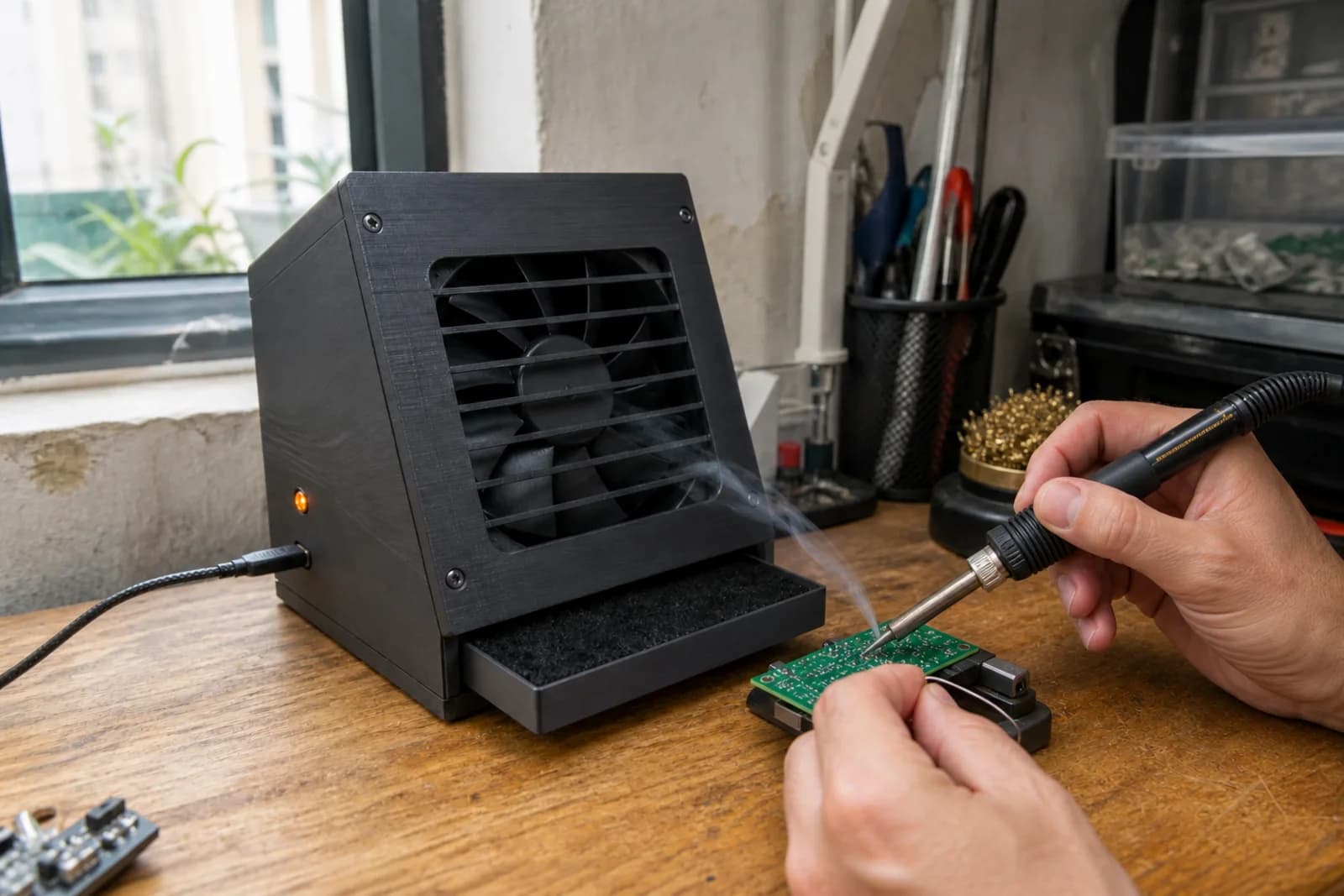
My workbench is not large. Once the soldering iron, magnifier, power supply, and a few component boxes are on it, there is barely any room left. A large fume extractor usually ends up pushed into a corner, and a distant extractor quickly becomes little more than a desk fan.
This note is for a small box built around a standard 120 mm PC fan, with an angled stand and a slide-out filter tray. The basic version only needs a switch. If I add an ESP32-C3, I only want it to do a few concrete jobs: change fan speed, stop the fan after a soldering session, and count operating hours for filter inspection.
This is not professional extraction equipment
The visible plume during electronics soldering mainly comes from flux. The UK HSE notes that rosin-based flux fume is a significant cause of occupational asthma and recommends extraction while keeping your head out of the plume. It also warns that bench-mounted boxes have limitations unless fitted with a HEPA filter.
I would treat this mini unit as source capture for short hobby soldering sessions. If you solder regularly, work with unknown materials, or use a poorly ventilated room, a proper local exhaust system or ducted exhaust is the better direction. A thin carbon pad may reduce odor, but it should not be presented as complete protection.
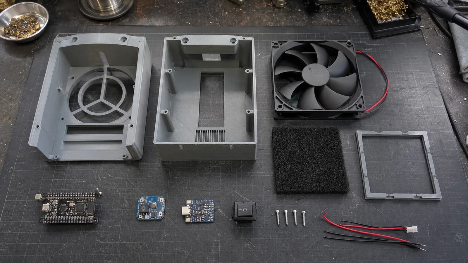
The mechanical build stays simple; the ESP32-C3 only adds speed control, a timer, and a filter reminder.
Parts for the first build
| Part | Practical choice |
|---|---|
| Fan | 120 x 25 mm, 12 V PWM fan; decent static pressure helps with filter resistance |
| Filter | 130 x 130 mm carbon pad cut to the tray, with room for a suitable upgraded filter layer |
| Controller | ESP32-C3 mini plus a driver suitable for the selected fan |
| Power | 12 V adapter or 12 V USB-C PD trigger, rated for the fan and electronics |
| Local control | One push button or small encoder, plus a status LED |
| Mechanical | PLA/PETG case, M3 screws, rubber feet, and fan guards |
For the fastest build, skip the ESP32 and use a switch with a small PWM controller. For the IoT version, I prefer a four-wire PC fan because its dedicated PWM input gives cleaner low-speed control and keeps the circuit straightforward.
What matters in the printed enclosure?
I would design around the real fan dimensions instead of forcing it into an elaborate shape:
- A 20-30 degree tilt aimed at the soldering area.
- A side-loading filter tray that does not require four screws for every change.
- A lightly flared intake without blocking too much fan area.
- Guards on both sides when loose cables share the desk.
- An ESP32 compartment outside the dirty airflow, with USB-C still accessible.
- Wide rubber feet so the unit stays put at full speed.
Print the filter tray first and check its clearance before committing to the whole enclosure. PETG is a comfortable workshop choice, although PLA is fine for a prototype that stays away from direct heat.
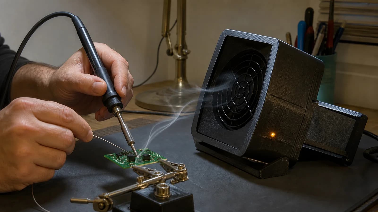
Keeping the intake roughly 10-20 cm from the joint usually matters more than running a distant fan at full speed.
Close placement beats a loud fan
I would place the intake about 10-20 cm from the joint, put a small amount of flux on scrap copper wire, heat it, and watch the plume. The smoke should turn clearly toward the intake before it reaches your breathing zone.
If the fan runs at 100% and smoke still passes your face, move the unit closer or adjust its angle first. More speed from the far side of the desk usually adds noise without fixing the capture problem.
Just enough IoT
Only three smart features feel worth keeping:
- A physical button cycles through 40%, 70%, and 100%.
- A 30-minute auto-off timer, while local control keeps working without Wi-Fi.
- An operating-hour counter with a filter inspection reminder, perhaps every 40 hours.
A minimal ESPHome starting point looks like this:
output:
  - platform: ledc
    pin: GPIO4
    frequency: 25000 Hz
    id: fan_pwm

fan:
  - platform: speed
    output: fan_pwm
    name: "Solder Fume Extractor"
    speed_count: 3
    restore_mode: ALWAYS_OFF
This is only the control outline. The electrical interface must match the selected fan, and a 12 V fan must never be powered directly from an ESP32 pin. I would also leave out the VOC sensor in version one. A gas sensor sitting in concentrated flux fumes can produce interesting numbers that are difficult to interpret, while intake distance and filter condition have a more direct effect on capture.
First-build checklist
- Verify power polarity and current capacity before connecting the ESP32.
- Check that the fan does not rub the enclosure at any speed.
- Fit guards so loose wires cannot reach the blades.
- Test the smoke path at several real soldering positions.
- Make the filter tray seal around its edges without becoming difficult to remove.
- Write the installation date on the filter instead of trusting only the hour counter.
- Keep using room ventilation whenever possible.
I would judge the first build through a few real soldering sessions, not just a neat parts photo. If it pulls smoke out of my breathing path at 10-20 cm, the tray is not annoying to service, and the box does not steal desk space when stored, then it is worth refining the second enclosure around my actual bench.
References
Share
Keep exploring
Read next
Related articles
A smart thermostat that learns how your room warms up
Notes on building an ESP32 smart thermostat that learns a room's heating rate, starts at the right time, and keeps safety control local.
A camera-free desk clock that indicates sleep quality
Notes for an ESP32 bedside clock that uses CO2, temperature, light, and bed presence to explain why a night felt off, without putting a camera in the bedroom.
A fridge and freezer temperature alert device for power outages
Notes for a small ESP32 box with two DS18B20 probes and Home Assistant alerts, meant to catch a warming fridge or freezer after a power outage.