

ESP32 Won't Start? 18 Common Problems and Fixes – Part 1
How I troubleshoot eight common ESP32 problems: flashing, boot mode, brownouts, serial, GPIO, I2C, SPI, and custom PCB bring-up.
Share
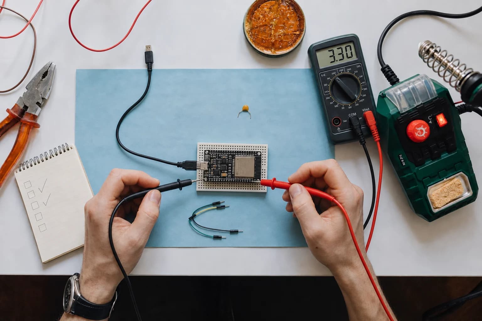
ESP32 failures can feel random: changing the cable suddenly fixes flashing, enabling Wi-Fi causes a reset, or a sensor that worked yesterday no longer responds today. I have spent too much time editing code when the real cause was a charge-only USB cable or a module pulling a boot pin to the wrong level.
Part 1 stays at the lowest layers: power, startup, firmware flashing, hardware connections, and custom PCB bring-up. Crashes, watchdogs, memory, and networking belong in Part 2.
Exact pins differ among the original ESP32, C3, S3, C6, and third-party boards, so open the pinout or schematic for the board on your desk before moving wires.
Troubleshoot from the bottom up
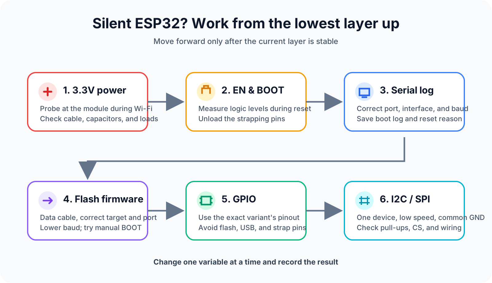
Working from the lowest layer upward prevents firmware changes when the real fault is power or wiring.
I normally work in this order:
Power → EN/BOOT → serial log → flashing → GPIO → I2C/SPI
If the 3.3V rail is collapsing, changing a display library will not help. Once power and the boot log are reliable, pin mapping and drivers become reasonable suspects.
1. Flashing fails with Failed to connect or No serial data received.
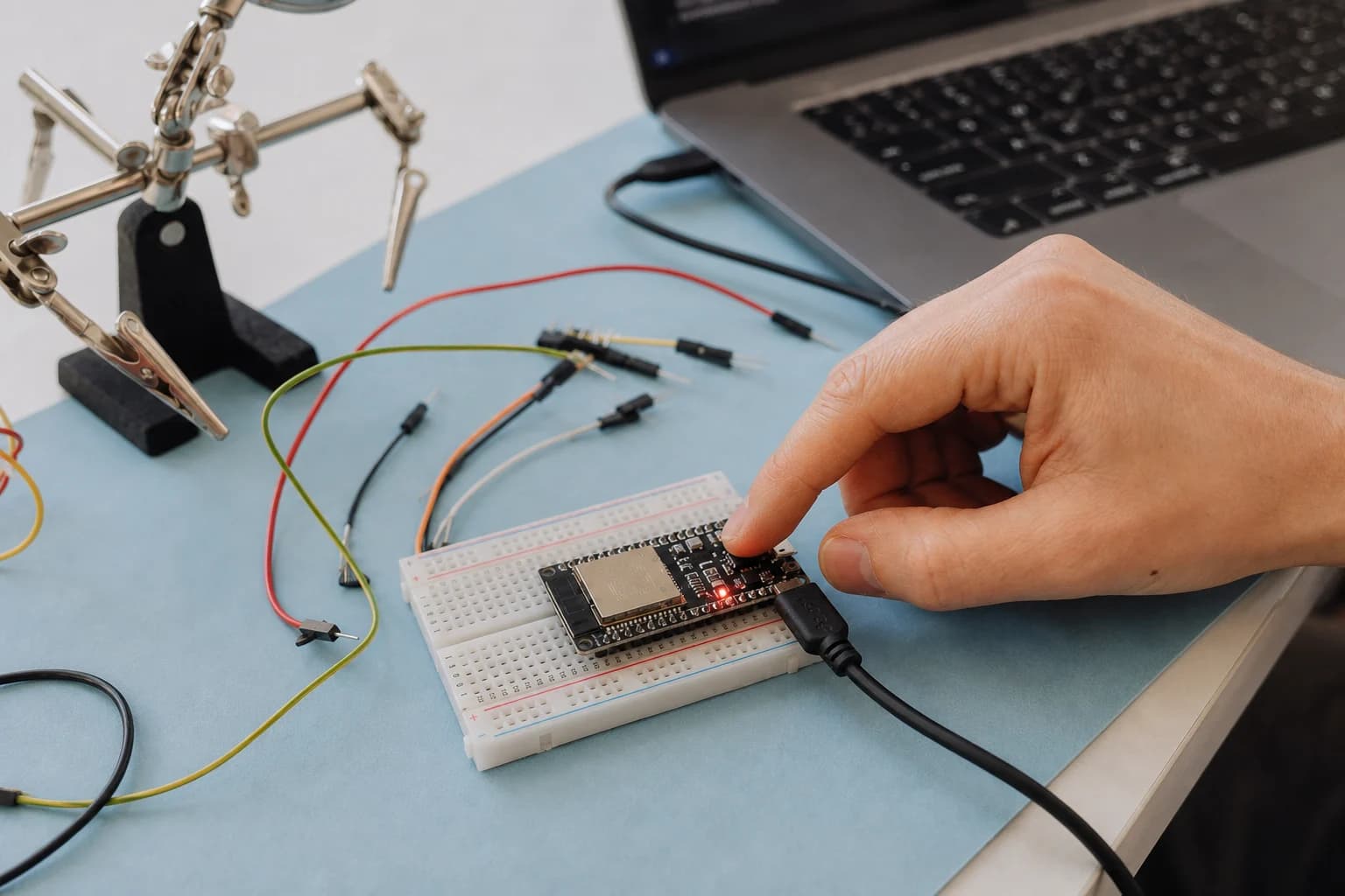
When esptool cannot connect, reduce the setup to the board, a known data cable, and the correct serial port.
Neither message proves that the chip is dead. The esptool troubleshooting guide lists several layers that can fail: serial-port selection and access, another program holding the port, unstable power, RX/TX wiring, or the chip not entering download mode.
I use this short sequence:
- Disconnect external modules and leave only the ESP32 and USB.
- Select the correct board, chip target, and serial port again.
- Close Serial Monitor and any other application using that port.
- Try a cable that is known to carry data, then try another USB port.
- Lower the flashing baud rate if writes fail partway through.
- If auto-reset fails, hold
BOOT, press and releaseEN/RESET, start flashing, and then releaseBOOT.
On boards using native USB, including some ESP32-S3 and C3 designs, application firmware can reconfigure the USB pins and make the port disappear. Manually entering the ROM download mode is then a sensible recovery step. Do not reinstall the entire toolchain before ruling out the cable, port, and boot mode.
2. The board runs only while BOOT is held, or starts in the wrong mode
ESP32 chips sample strapping pins during reset to choose the boot mode and some hardware settings. On the original ESP32, holding GPIO0 low during reset selects the serial bootloader; newer families use different pins and conditions. A sensor, button, or external pull resistor can therefore stop the application from booting even after a successful flash.
Common signs include:
Wrong boot mode detectedduring flashing.- A board that returns to download mode after flashing.
- A board that starts only after you remove a peripheral or touch
BOOT. - A DevKit that works while a custom PCB using the same module does not.
Measure BOOT and EN while reset is happening, not only after the board has settled. Check pull resistors, the DTR/RTS auto-reset circuit, and the EN capacitor against the reference schematic for your exact chip. I avoid placing an essential load on a strapping pin until I know how that load behaves during power-up.
3. Brownout detector was triggered, or Wi-Fi causes resets
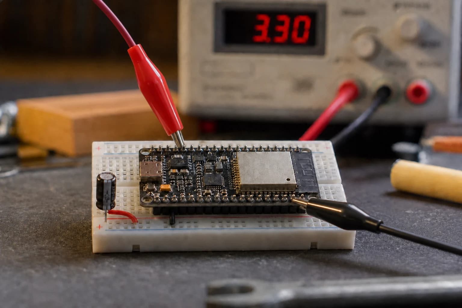
Measure at supply pins close to the board instead of trusting only the bench-supply display.
A brownout is not a mysterious firmware exception. The detector resets the chip when its supply falls below a safe level. Wi-Fi often exposes the fault because radio activity creates fast current steps; a multimeter may still show a steady 3.3V average while the rail briefly dips.
I check whether:
- The 3.3V source can handle peak current. Espressif recommends at least a 500mA supply for the original ESP32 and at least 10µF at the board's power entrance.
- The USB cable is long, thin, damaged, or loose.
- 100nF decoupling is close to the supply pins and bulk capacitance is close to the module.
- A motor, relay, speaker, or backlight shares a narrow supply path with the ESP32.
- Voltage drops at the module's actual
3V3andGNDpins during Wi-Fi transmission.
With an oscilloscope, trigger around the reset. With only a multimeter, substitute a known-good supply, shorten the wires, and remove external loads. Disabling the brownout detector hides the warning; it does not repair a weak rail.
4. Serial Monitor is blank or shows garbage
I check the serial log before I check an LED. A blank monitor can mean three different things: there is no boot output, data is decoded at the wrong baud rate, or the log uses another interface.
The original ESP32 emits its ROM boot log over UART0. Newer chips and boards may use USB Serial/JTAG or USB CDC, depending on their design and firmware configuration. Try these checks:
- Select the port that appears when the board is connected.
- Use the baud rate configured by the project; ESP-IDF application logs commonly use
115200. - With an external USB-UART adapter, cross
TX → RX,RX → TX, and connect a common ground. - Reset the board and capture the entire first log, not only its last line.
- Print
esp_reset_reason()early when using ESP-IDF.
A few unreadable bytes before a clean application log can come from a ROM baud rate that differs from the monitor setting; it does not automatically indicate a damaged chip. If TX has no activity at all, return to power, EN, and boot mode.
5. The wrong GPIO makes an LED, input, or entire board fail
Assuming every GPIO is interchangeable is a common mistake when moving between ESP32 families. Depending on the chip and module, some pins are input-only, connected to flash or PSRAM, sampled as strapping pins, used by native USB, or not routed to a header. ESP32 logic is also 3.3V; you should not assume that a GPIO is 5V tolerant.
Before blaming a library, I verify four things:
- The GPIO number in code matches the board label and schematic.
- Flash, PSRAM, USB, or another peripheral does not already own that pin.
- The external load does not change a strapping level at reset.
- An input has a deliberate pull-up or pull-down instead of floating.
For a new PCB, begin with a slow output toggle or a simple input read on a safe pin. Do not bring up a display, SD card, and interrupt source at the same time; a failure then has too many possible layers.
6. I2C finds no device or times out
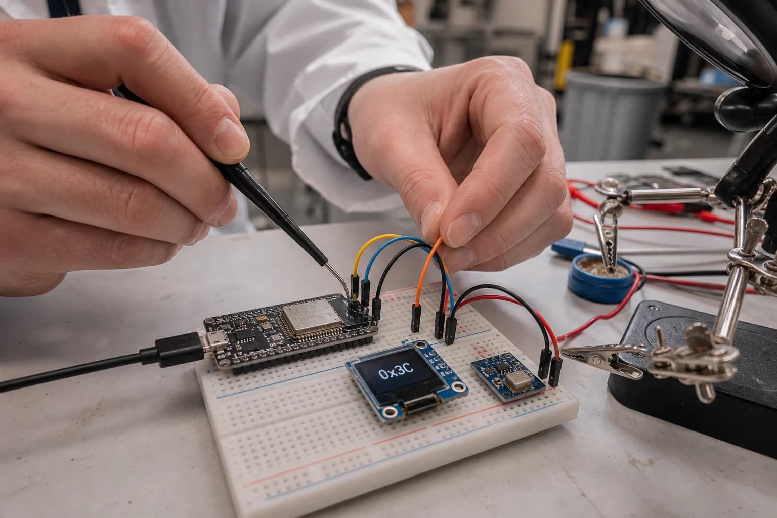
Verifying wires, common ground, and the pin map often saves more time than rewriting code.
I2C needs only SDA and SCL, but pull-ups, wire capacitance, and address conventions matter. ESP-IDF's i2c_tools example is useful because you can configure pins and speed, then run i2cdetect before writing a sensor driver.
My short checklist is:
- Confirm that SDA and SCL are not swapped and every board shares ground.
- Scan the 7-bit address; do not blindly copy an 8-bit address from a datasheet.
- Check whether each breakout already contains pull-ups. Several boards in parallel can make the effective pull-up too strong, while no pull-up produces slow rising edges.
- Reduce the bus from 400kHz to 100kHz and shorten the wires.
- Measure the idle state: SDA and SCL should normally be high. If one remains low, remove devices one by one.
ESP-IDF documentation gives 1–10kΩ as a common pull-up range and 2–5kΩ as a useful starting range, but bus capacitance and the number of modules determine the final value. Seeing an address in a scan proves that ACK works; the driver can still use the wrong register map, timing, or logic voltage.
7. SPI displays, and SD cards remain silent
SPI has no addressing phase like I2C. A wrong CS, incorrect mode, or another device holding the bus may simply look like no response. I reduce the setup to one peripheral and verify:
SCLK,MOSI,MISO, andCSdirection and pin mapping.- Each device has a separate
CS, and unused chip-select lines stay inactive. - The SPI mode (
CPOL/CPHA) and clock rate match the datasheet. - Clock wires are short, the ground return is sound, and the module uses the correct supply voltage.
- The SD card's startup current and required pull-ups are supported by the breakout.
Start slowly, connect one peripheral, and run the closest official example. Add devices back one at a time. A logic analyzer makes this much clearer: clock without CS suggests configuration, while valid CS and clock with a motionless MISO line points toward wiring, power, mode, or reset state.
8. The dev board works, but the custom PCB does not
I see this often when moving from a DevKit to the first custom PCB. The firmware is nearly unchanged and the module may be identical, but the custom board no longer has the regulator, capacitors, auto-reset circuit, and USB bridge that the DevKit manufacturer already handled. Treat this as hardware bring-up before rewriting application code.
I first measure the supply at the module and watch EN during power-up and reset. Check the pull resistors on EN and BOOT, the EN capacitor, input bulk capacitance, and decoupling capacitors close to the supply pins. A correct schematic value is not enough when a power trace is narrow, a capacitor is far away, or the ground return takes a long path.
Next, verify the flashing path:
- With USB-UART, confirm crossed
TX/RX, a common ground, and that the DTR/RTS circuit really drivesEN/BOOTin the required sequence. Leave test points so BOOT and reset can be controlled manually. - With native USB, verify the chip's exact
D+andD-pins, the reference-design series resistors, VBUS handling, and the return path. Route the pair together, minimize vias, and keep a continuous reference plane below it.
For a module with a PCB antenna, place the antenna beyond the carrier-board edge when possible. Keep copper, traces, and components out of the module-specific clearance area, and consider batteries, metal shields, and the product enclosure above it. The board may boot normally while Wi-Fi or BLE range remains poor when this area is compromised.
Finally, disconnect or isolate peripherals attached to strapping pins, EN, BOOT, and flash or PSRAM pins. A level shifter, pull-up, display, or sensor can produce the correct level after startup but the wrong level while reset is sampled. On an early revision, I like to leave 0 Ω resistors or jumpers so each branch can be isolated; if the board boots after one branch is removed, you have narrowed the fault without replacing the ESP32.
A ten-minute checklist before editing code
- Remove external loads and use a known-good data cable and power source.
- Confirm chip target, board, port, and that no application owns the serial port.
- Check
EN,BOOT, and strapping pins during reset. - Save the complete boot log and reset reason.
- Measure 3.3V at the module while the failure occurs.
- Compare wiring with the exact ESP32 variant, not a random online pinout.
- For I2C or SPI, lower the speed and keep only one device connected.
- Change one variable at a time and record the result.
Conclusion
Most ESP32 bring-up problems become harder when we jump to software too early. Following power → boot → log → flash → GPIO → bus lets each test eliminate a group of causes and makes troubleshooting far less dependent on luck.
Part 2 will continue with Guru Meditation errors, backtraces, watchdogs, stack and heap issues, FreeRTOS, Wi-Fi/BLE, deep sleep, and OTA.
References
Share
Keep exploring
Read next
Related articles
What Is a MEMS Microphone? From a Silicon Diaphragm to ESP32 Audio
Learn how MEMS microphones work, how analog, PDM, and I2S outputs differ, and how to avoid PCB, power, and acoustic-port mistakes.
ESP32 Battery Power Design: From USB-C Charging to the 3.3V Rail
Review an ESP32-S3 battery power path from USB-C and TP4056 charging to protection, load sharing, 3.3V regulation, and load budget.
Complete Hardware Architecture for an ESP32-S3 Mochi Robot
A practical breakdown of ESP32-S3 Mochi Robot hardware: display, touch, I2S microphone, amplifier, speaker, battery, charging, and GPIO.