

What Is a MEMS Microphone? From a Silicon Diaphragm to ESP32 Audio
Learn how MEMS microphones work, how analog, PDM, and I2S outputs differ, and how to avoid PCB, power, and acoustic-port mistakes.
Share
A MEMS microphone looks like a metal IC only a few millimeters wide, yet it contains both a moving mechanical structure and circuitry that turns motion into a useful signal. Its small footprint, manufacturing consistency, and surface-mount package make it a natural fit for phones, earbuds, laptops, cameras, IoT devices, and compact robots such as Mochi.
One distinction clears up much of the confusion: MEMS describes the transducer technology, not the electrical interface. When I choose one for an ESP32 project, I ask three questions: how is sound converted, what data reaches the ESP32, and how will sound travel through the enclosure to the microphone? Your answer may lead to an analog, PDM, or PCM/I2S part.
What is inside a MEMS microphone?
A typical capacitive MEMS microphone contains three functional elements:
- A silicon diaphragm that moves by a tiny amount as sound pressure changes.
- A backplate that forms a capacitor with the diaphragm. Motion changes the capacitance.
- An ASIC that biases the sensor, amplifies its output, and produces an analog or digital signal.
Sound enters through the acoustic port and moves the diaphragm. The ASIC measures the resulting capacitance change and turns it into a signal the rest of the system can consume:
Sound pressure → MEMS diaphragm → capacitance change → ASIC → analog / PDM / I2S
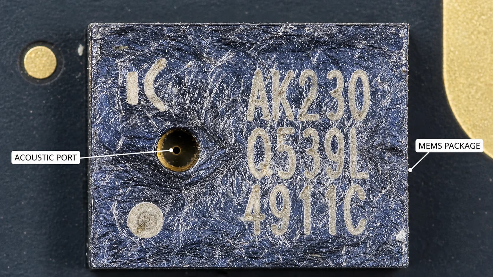
That is why a microphone cannot be treated as just a component with a hole in it. The package, inlet, air cavity, gasket, PCB, and enclosure all contribute to the measured frequency response.
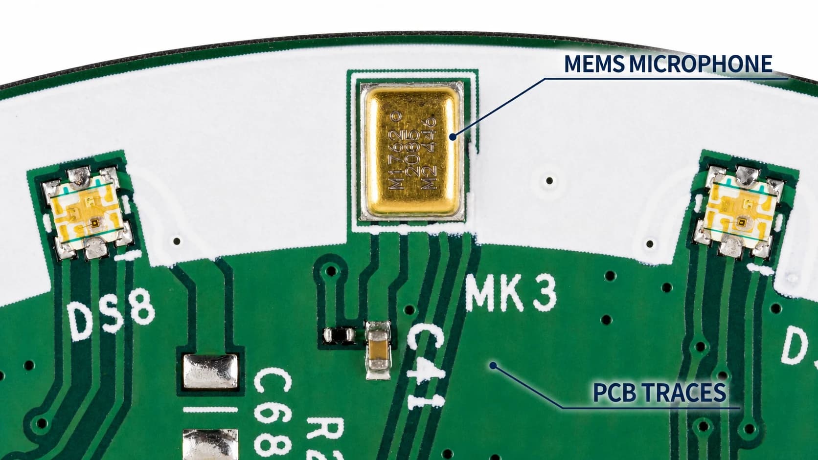
The package is only the visible shell; a MEMS transducer and signal-processing ASIC sit inside.
How does MEMS compare with electret and dynamic microphones?
Dynamic microphones use a coil and magnet. Electret condenser microphones use a charged capacitive element. Both remain useful technologies, but they are not ideal for every compact embedded product.
MEMS microphones offer several practical advantages:
- small, low-profile surface-mount packages;
- tighter part-to-part matching, especially useful in arrays;
- straightforward integration of several microphones on one PCB;
- digital variants that avoid routing a low-level analog signal across the board;
- form factors and assembly processes suited to volume manufacturing.
The tradeoff is that assembly, layout, and acoustic design matter enormously. A strong datasheet cannot rescue a port blocked by adhesive, a leaking gasket, or a microphone placed beside a switching inductor and loudspeaker.
The three output types you will encounter
Analog MEMS microphones
An analog microphone outputs a voltage that follows the captured waveform. The system needs an ADC and must account for biasing, gain, supply noise, grounding, and the ADC input range.
The signal chain is intuitive and works well with many codecs. Its weak point is the low-level analog path between microphone and converter, which can collect noise when traces are long or power and grounding are poorly controlled.
PDM MEMS microphones
PDM is a high-clock-rate, one-bit digital stream. Pulse density represents the instantaneous signal level; filtering and decimation are required to obtain ordinary PCM samples.
PDM works well for compact arrays, but the processor and firmware must support the exact mode. ESP32-S3 supports PDM reception and hardware conversion on specific I2S resources and configurations. Do not assume every ESP32 family or I2S port offers the same converter.
I2S digital MEMS microphones
Breakouts such as the INMP441 are commonly called I2S microphones because they output multi-bit PCM samples with I2S timing. A typical mono connection includes:
VDDandGND;BCLKorSCKfor the bit clock;WSorLRCLKfor the left and right slots;SDorDOUTfor sample data;L/RorSELto select the slot driven by that microphone.
I2S is approachable on ESP32 because the samples are already represented as multi-bit words. Digital signaling still needs good engineering: long clocks, broken return paths, and a noisy microphone rail can produce errors or raise the noise floor.
For a deeper treatment of clocks, slots, buffers, and bidirectional audio, see the ESP32-S3 I2S audio architecture guide.
Six specifications worth reading
1. Interface and format
Confirm whether the output is analog, raw PDM, or PCM/I2S. For a digital part, check the sampling edge, word width, slot selection, allowed clocks, and what the data pin does while the microphone does not own a slot.
2. Sensitivity
Sensitivity states the output level for a standard acoustic input, commonly 94 dB SPL at 1 kHz. Analog microphones normally use dBV/Pa, while digital microphones often use dBFS. Values with different units are not directly comparable.
3. Signal-to-noise ratio
A higher SNR gives more separation between the reference signal and the microphone's own noise floor. It is not the only selection criterion: room noise, vibration, fans, and acoustic leakage can easily outweigh a few decibels on a datasheet.
4. Acoustic overload point
AOP describes the maximum sound pressure the microphone handles before distortion crosses a specified threshold. For a microphone near a loudspeaker, buzzer, or motor, AOP may matter more than a small SNR advantage.
5. Frequency response
Voice control does not require a perfectly flat response to 20 kHz, but it benefits from consistent performance across the speech band. Inspect the low-frequency roll-off as well: gasket and port geometry can move the real product far away from the datasheet fixture.
6. Voltage, current, and power modes
Not every MEMS microphone can connect directly to 3.3 V. Some parts require a lower rail or offer several performance modes. Startup time also matters when firmware power-cycles the microphone to extend battery life.
Top port and bottom port affect the whole product
With a top-port part, sound enters through the top face of the package. The enclosure needs a correctly aligned opening and gasket.
With a bottom-port part, sound enters through the package underside, so the PCB needs a matching hole. Copper, solder-mask, paste, and mechanical keepouts must follow the manufacturer's footprint. Solder paste, flux, adhesive, dust, or conformal coating in the inlet may permanently damage the microphone or alter its response.
The sound inlet belongs to the acoustic path, so its PCB and enclosure geometry cannot be treated as an afterthought.
The path between enclosure and microphone should be sealed, short, and geometrically controlled. Even a small leak between the gasket and PCB can reduce capture level, thin out the response, or make nominally identical microphones behave differently in an array.
PCB checklist for an ESP32 microphone
- Place the recommended supply bypass capacitor close to the microphone.
100 nFis common, but it is not a substitute for the part's datasheet. - Keep
BCLK,WS, andDOUTshort with a continuous return path, away from switching nodes. - Separate the microphone from the Wi-Fi antenna, inductors, buck converters, class-D amplifiers, and speaker traces.
- Follow copper, solder-mask, and paste keepouts around the acoustic inlet.
- Keep vias, silkscreen, adhesive, and conformal coating away from the port.
- Reduce mechanical coupling from the loudspeaker into the PCB and enclosure.
- Check whether a hand, tabletop, or cosmetic feature blocks the microphone in normal use.
- Test the assembled enclosure. A bare breakout on a bench validates the interface, not the final acoustics.
Choosing a microphone for Mochi or an ESP32 prototype
For a prototype, an I2S breakout such as INMP441 is convenient. It lets you validate the driver, sample format, buffering, voice-activity detection, and upload path before committing to a custom PCB.
For production hardware, do not select a component only because the breakout worked. Choose an active part with a clear datasheet, suitable sourcing, a verified footprint, and performance that matches the real speaking distance. If you choose PDM, confirm the SoC's PDM RX resources and budget the PDM-to-PCM processing path.
In a robot with both speaker and microphone, mechanical placement often matters more than upgrading to a more expensive microphone. Measure with the speaker silent, during playback, and while Wi-Fi is transmitting. Those tests separate self-noise, supply noise, RF coupling, mechanical vibration, and acoustic echo.
Conclusion
A MEMS microphone is a complete sensing system built from a silicon diaphragm, signal-processing ASIC, and acoustic package. Selecting the correct interface solves only the electrical connection. Clear capture also depends on clean power, disciplined layout, a controlled sound inlet, a sealed gasket, and sensible placement inside the enclosure.
I2S is usually the easiest starting point on ESP32, while PDM can be a strong fit when the hardware supports the required receive and conversion path. In either case, read the exact microphone datasheet and the documentation for the exact ESP32 target before freezing the schematic and PCB.
References
- STMicroelectronics: MEMS microphones
- ST AN4426: Tutorial for MEMS microphones
- Analog Devices: Understanding Microphone Sensitivity
- ESP-IDF: I2S on ESP32-S3
Image credits and license
The cover and PCB close-up are adapted from the Wikimedia Commons Amazon Echo Dot microphone board and its microphone detail. The acoustic-port image is adapted from the Akustica AKU230 MEMS microphone photograph. Original photographs by Raimond Spekking, licensed under CC BY-SA 4.0; the adaptations in this article remain under the same license.
Share
Keep exploring
Read next
Related articles
Complete Hardware Architecture for an ESP32-S3 Mochi Robot
A practical breakdown of ESP32-S3 Mochi Robot hardware: display, touch, I2S microphone, amplifier, speaker, battery, charging, and GPIO.
ESP32-C3 or ESP32-S3: Which Chip for a Robot with a Screen and Audio?
Comparing ESP32-C3 and ESP32-S3 on GPIO, RAM, PSRAM, USB, I2S, and LVGL headroom, with a concrete recommendation for a basic Mochi build and a Mochi AI build.
ESP32 Battery Power Design: From USB-C Charging to the 3.3V Rail
Review an ESP32-S3 battery power path from USB-C and TP4056 charging to protection, load sharing, 3.3V regulation, and load budget.