

5G IoT with ESP32: Connect NB-IoT & LTE-M from Modem to MQTT
A practical ESP32 guide to integrating an NB-IoT/LTE-M modem: choose the network, power it safely, wire UART, use TinyGSM and send first telemetry.
Share
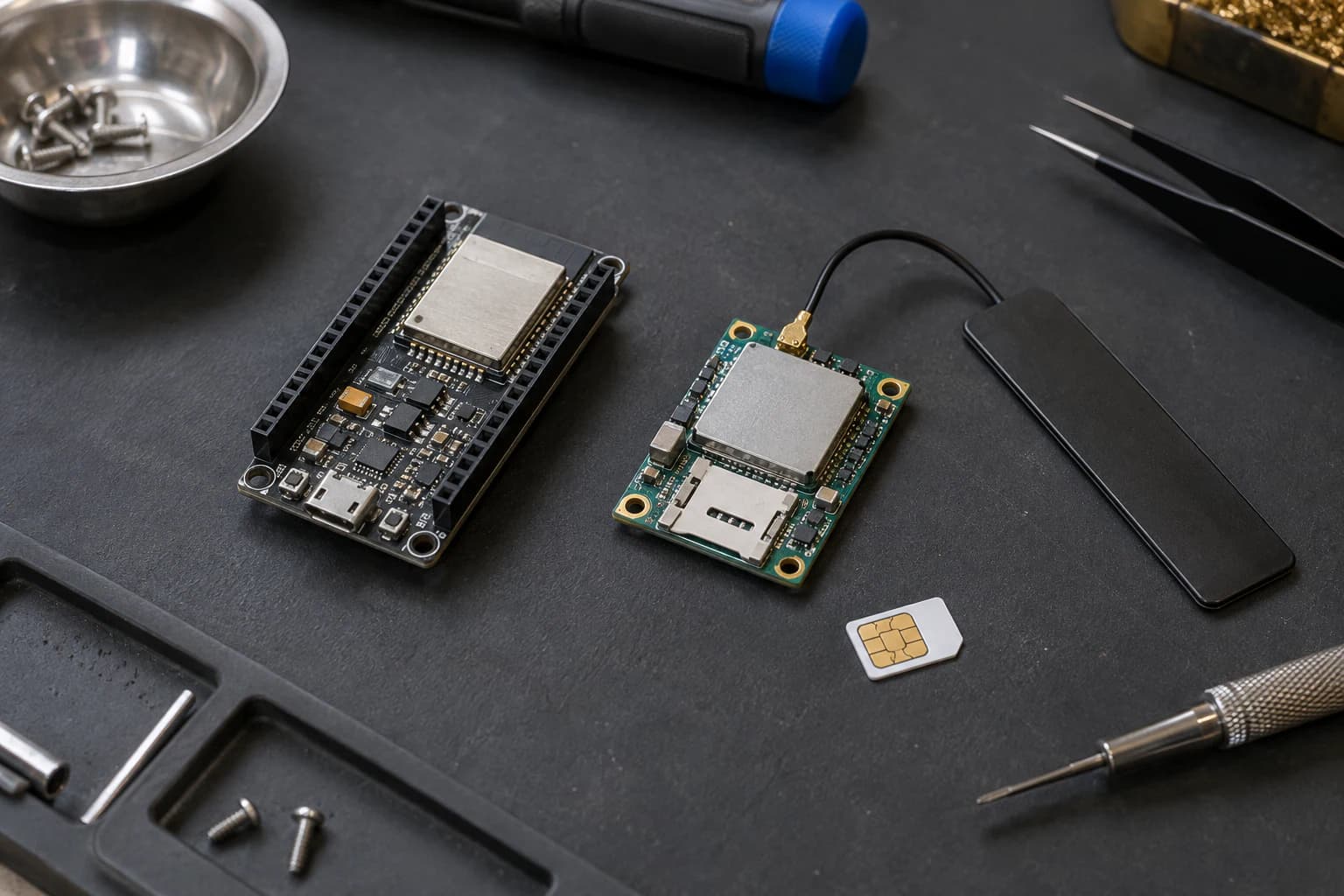
When Wi-Fi cannot reach a sensor location, I do not automatically add another repeater. A small cellular modem that sends a few bytes every few minutes is often the tidier option. This is the short path to pairing an ESP32 with an LPWA modem such as a SIM7080G and sending telemetry to MQTT or HTTP.
One naming note first: NB-IoT and LTE-M are 4G/LTE-standardised LPWA technologies, not phone-style high-bandwidth “5G.” “5G IoT” here means the wider cellular-IoT direction for low-power, wide-area devices in the 5G era. A SIM7080G is great for telemetry—not video streaming.
The open-source starting point
I use TinyGSM as the transport layer. This open-source Arduino library supports SIM7000, SIM7070/SIM7080, Quectel BG95/BG96, u-blox SARA and ESP32 HardwareSerial. For an integrated board, the LilyGO T-SIM7080G examples are also worth reading: they cover AT testing, GNSS, sleep, and NB-IoT/LTE-M examples for that board.
I would not clone either project unchanged and call it a tutorial. The reliable sequence is what matters: power modem → check SIM → register network → open PDP/APN → transfer data. Radio setup and power pins still need to match your exact board, modem firmware and carrier.
Choose NB-IoT or LTE-M before buying
| Your device needs | Lean toward | Practical note |
|---|---|---|
| Tiny packets, long battery life, deeper indoor reach | NB-IoT | Latency can be high; not for immediate control. |
| More frequent telemetry, mobility, small OTA, quicker responses | LTE-M / Cat-M1 | Often friendlier for moving nodes; always check coverage. |
| Images, audio, heavy real-time dashboards | Neither | Consider LTE Cat-1/4G or Wi-Fi. |
This is not a datasheet-only decision. Before ordering hardware, I ask the SIM provider three things: does the deployment area have NB-IoT or LTE-M, which SIM/APN is approved, and does my modem have the required bands and firmware? A “global” modem does not create coverage.
Minimum hardware
- An ESP32 DevKit or ESP32-S3.
- A SIM7080G/SIM7070G, or another TinyGSM-supported modem, plus the correct LTE antenna and LPWA-enabled data SIM.
- A dedicated supply that matches the breakout requirements. For cellular modem breakouts, I favour a stable 5 V, 2 A input when the board documentation calls for it; do not draw modem power from an ESP32 3V3 pin.
- UART wires and a common ground. If a breakout does not explicitly support 3.3 V logic, add suitable level shifting.
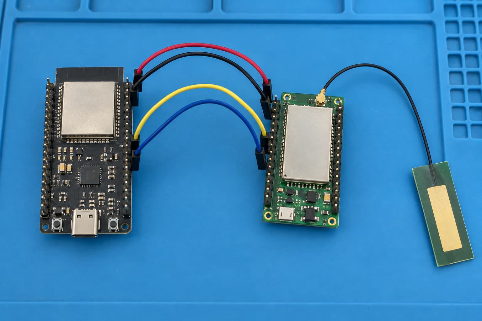
Cross TX/RX, share ground, and supply the modem separately as the breakout requires.
Wiring and system flow
A common ESP32 UART2 example is modem TXD → GPIO16 (RX2), modem RXD → GPIO17 (TX2), and GND ↔ GND. PWRKEY and reset vary by breakout, so take them from that board’s schematic or documentation—never infer them from the modem family name.
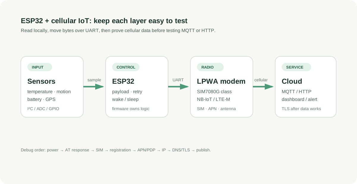
Separating sensor, modem, network and application layers narrows faults faster.
The diagram separates responsibilities for easier debugging. ESP32 owns the sensors, wake/sleep schedule and payload. The modem owns cellular registration and the PDP context. MQTT or HTTP sit above that; if data is connected but publish fails, investigate DNS, TLS and the broker before rewiring UART.
TinyGSM sketch: prove data first, add MQTT next
Install TinyGSM from Library Manager. Replace YOUR_APN, SIM PIN and UART pins for your board. This intentionally opens a data session and prints an IP before it attempts MQTT. That small checkpoint makes it clear whether a fault is in SIM, network or application code.
#define TINY_GSM_MODEM_SIM7080
#define TINY_GSM_RX_BUFFER 1024

#include <TinyGsmClient.h>

constexpr int MODEM_RX = 16; // ESP32 receives modem TXD
constexpr int MODEM_TX = 17; // ESP32 sends modem RXD
constexpr uint32_t MODEM_BAUD = 115200;
const char APN[] = "YOUR_APN";
const char SIM_PIN[] = "";

HardwareSerial SerialAT(2);
TinyGsm modem(SerialAT);

void setup() {
  Serial.begin(115200);
  SerialAT.begin(MODEM_BAUD, SERIAL_8N1, MODEM_RX, MODEM_TX);

  // Drive PWRKEY according to the breakout documentation before this point.
  if (!modem.init()) Serial.println("Modem init failed");
  if (strlen(SIM_PIN) && modem.getSimStatus() != 3) modem.simUnlock(SIM_PIN);
  if (!modem.waitForNetwork(180000L)) Serial.println("Network registration failed");
  if (!modem.gprsConnect(APN, "", "")) Serial.println("PDP/APN failed");

  Serial.print("IP: ");
  Serial.println(modem.localIP());
}

void loop() {}
Once it has an IP, TinyGsmClient client(modem); is the bridge to an HTTP or MQTT client. For MQTT, I keep payloads small, choose QoS deliberately, and reconnect with backoff. Repeatedly calling connect() in poor coverage just makes diagnosis harder.
Power: why boards reset exactly when they transmit
Cellular modems draw current bursts while registering and transmitting. The familiar symptom is that AT works, but ESP32 brownouts or the modem reboots during attach/PDP. Measure at the modem power pins, use short leads, fit the bulk capacitance recommended by the board, and provide enough current. Attach the antenna before transmitting.
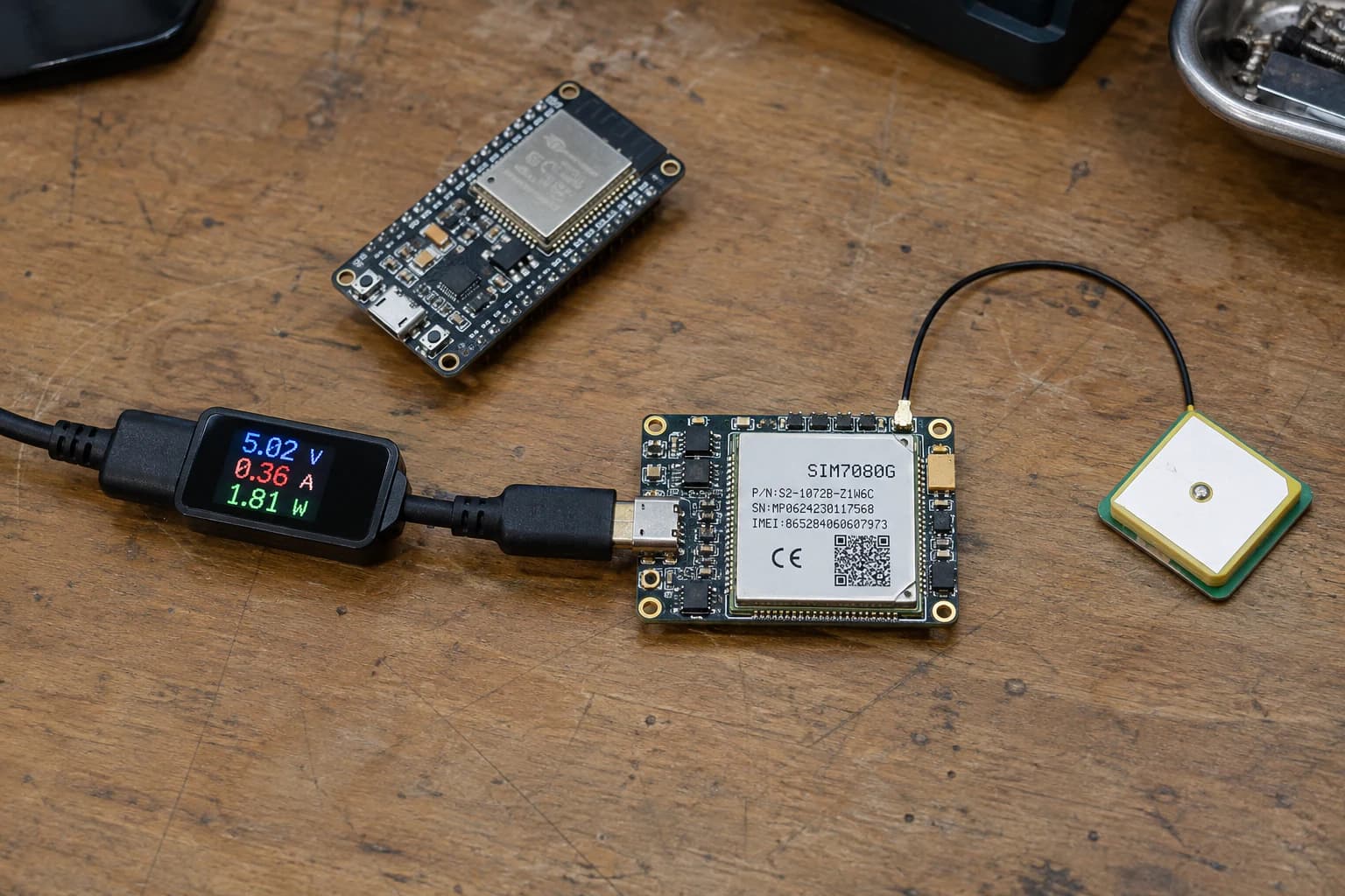
Measure voltage droop at the modem pins while it registers and transmits.
Do not optimise deep sleep before you have one stable transfer. Then try PSM/eDRX according to carrier support, measure real current, and verify that the modem wakes again. Initial attach can take much longer than Wi-Fi; a 10-second timeout often manufactures a difficult bug.
Ten-minute debug checklist
- Send
ATand seeOKin a serial monitor. - Confirm the SIM is detected, the PIN is correct and the LTE antenna is attached.
- Check network registration (the command varies by modem) and allow enough first-attach time.
- Confirm the APN is correct for the LPWA SIM; do not assume a phone-SIM APN works.
- Obtain an IP before testing DNS, HTTP or MQTT.
- If it resets while transmitting, measure supply droop before changing firmware.
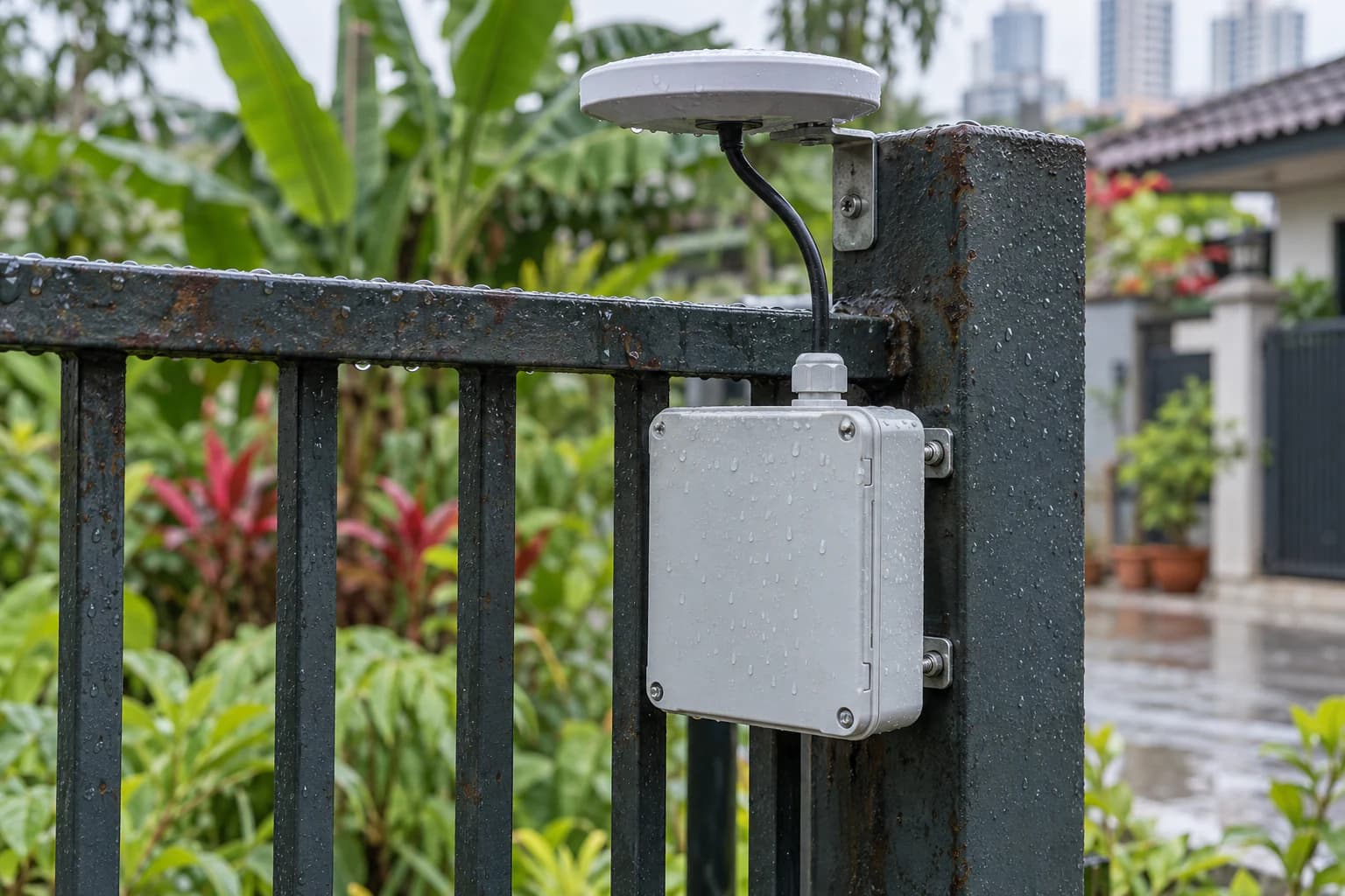
A small LPWA node can send telemetry from locations beyond Wi-Fi coverage.
What I would do next
For the first node, I would read one sensor and send a tiny JSON payload such as {"t":29.4,"v":3.98}. After it survives a few days at the actual installation site, I would add TLS, offline buffering, OTA and an enclosure. It costs one extra afternoon, but avoids debugging radio, battery, broker and firmware all at once.
References
Share
Keep exploring
Read next
Related articles
Real-Time Operating System (RTOS): FreeRTOS on ESP32
A beginner-friendly guide to using FreeRTOS on ESP32 for multitasking firmware with tasks, queues, notifications, mutexes, and practical debugging habits.
Industrial IoT with ESP32: Modbus and Real-Time Control
A practical guide to Modbus TCP, Modbus RTU over RS-485, and PLC communication with ESP32 for reliable industrial IoT prototypes.
Over-The-Air (OTA) Firmware Updates: Design & Implementation
A practical guide to designing safe OTA firmware updates for ESP32 and STM32, covering partitions, signed images, rollback, rollout control, and delta updates.