

Industrial IoT with ESP32: Modbus and Real-Time Control
A practical guide to Modbus TCP, Modbus RTU over RS-485, and PLC communication with ESP32 for reliable industrial IoT prototypes.
Share
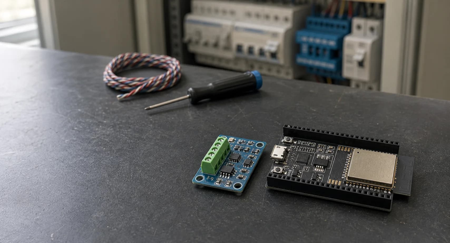
If you have worked with a PLC, a temperature controller, or an inverter, you have probably met Modbus. It is not a glamorous protocol, but it is still one of the most useful bridges between a small controller and industrial equipment.
In this note, I will use ESP32 as a small IIoT gateway: read process values from a PLC, write a limited set of commands back, and keep the real-time control path separate from Wi-Fi or cloud work. The examples are intentionally small so you can adapt them to a real machine without carrying a pile of unnecessary abstractions.
The role of ESP32 in an IIoT system
ESP32 is not a replacement for a safety PLC. I see it as a flexible edge controller for monitoring, protocol conversion, local HMI, diagnostics, or non-safety-critical commands. A typical boundary looks like this:
sensor / actuator <-> PLC <-> Modbus <-> ESP32 <-> MQTT / dashboard
The PLC should remain responsible for deterministic machine logic and safety interlocks. ESP32 can collect values, expose a simple dashboard, buffer data, or request a permitted operating mode. This boundary keeps a network outage from becoming a machine-control failure.
Modbus TCP and Modbus RTU: what changes?
Both variants share the same application model: a client sends a request, and a server returns data or an exception. The practical difference is the transport:
| Variant | Physical/network layer | What I pay attention to |
|---|---|---|
| Modbus TCP | Ethernet or Wi-Fi, normally TCP port 502 | IP address, Unit ID, reconnects, network timeouts |
| Modbus RTU | Serial line, commonly RS-485 | A/B polarity, termination, baud/parity, silent interval |
RTU frames use a CRC on the serial line. TCP uses the TCP/IP transport and does not carry the RTU CRC. That does not mean TCP is automatically secure: Modbus itself does not provide authentication or authorization, so keep the control network segmented and restrict who can write.
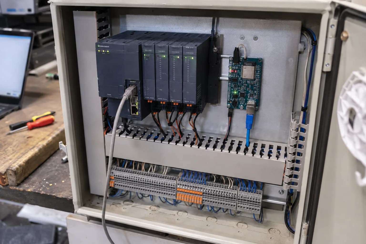
Start by proving the physical bus before debugging the register map.
A register map is a contract
The hardest part is often not the ESP32 code. It is agreeing on what a register means. Before writing a driver, ask the PLC documentation for a table like this:
| Meaning | Modbus area | Address in the vendor table | Type | Scale |
|---|---|---|---|---|
| Tank temperature | Holding register | 40011 | uint16 | value / 10 |
| Pump command | Coil | 00001 | bool | 0 or 1 |
| Alarm word | Input register | 30021 | uint16 | bit field |
The address shown as 40011 is a human-facing convention in many manuals. The request PDU commonly uses a zero-based offset, so the actual offset may be 10. Do not guess this. Test one known-good value and document whether the PLC expects zero-based or one-based addressing.
For values wider than 16 bits, also confirm word order and byte order. A float can be represented as two registers in more than one order, and a perfectly healthy Modbus link can still produce nonsense if the endianness is wrong.
Modbus RTU with ESP32 and RS-485
The UART on ESP32 is not an RS-485 transceiver. You still need a suitable transceiver and a design that matches the voltage, isolation, and environment of the machine. On the bus:
- Connect A to A and B to B according to the transceiver datasheet; labels are unfortunately not universal.
- Use a twisted pair and keep the stub short.
- Add termination at the two physical ends of the bus, not at every node.
- Make sure the biasing strategy is defined once for the segment.
- Share a reference or use isolation when the installation requires it.
- Start with the exact baud rate, parity, stop bits, and slave ID from the PLC manual.
With ESP-IDF, the official ESP-Modbus component provides serial master/slave examples and supports RS-485 as well as TCP transports. The component API has changed across major versions, so pin the version in your project and read the matching example before copying an older snippet.
Modbus TCP: easier wiring, same discipline
TCP removes the RS-485 wiring problems, but it does not remove protocol problems. Give the PLC a stable address, set a finite connect and response timeout, and make reconnect behavior explicit. A TCP master still needs a correct Unit ID when it talks to a gateway or a device that uses it.
For a first test, I usually do this:
- Ping or otherwise verify the network path.
- Read one documented holding register.
- Compare the value with the PLC display.
- Read a block of adjacent registers.
- Only then attempt a write to a harmless test register.
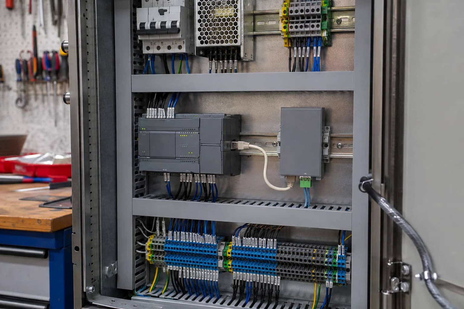
An enclosed gateway keeps prototype wiring out of the control cabinet and gives every cable a defined termination.
Keep control timing separate from the network
This is the part that makes a prototype feel reliable. Do not let a blocking Wi-Fi reconnect or a slow Modbus request directly own a relay output.
One simple split is:
control task (fixed period) -> consumes validated setpoints -> drives outputs
modbus task                -> reads/writes registers -> publishes snapshots
network task               -> MQTT/HTTP, logs, OTA, diagnostics
The control task should have a clear period, a bounded amount of work, and a defined stale-data policy. If the Modbus task has not delivered a fresh value in time, the control task should move to a known fallback state rather than silently using old data.
For FreeRTOS, use queues or small structs to pass snapshots between tasks. Protect shared state with a mutex or, even better, pass ownership of a complete snapshot. Avoid holding a lock while waiting on the network. That one rule removes a surprising number of intermittent timing bugs.
A small ESP-IDF-shaped skeleton
The exact ESP-Modbus v2 API depends on the component version, so this is a structure rather than a drop-in application:
typedef struct {
    uint16_t temperature_x10;
    bool pump_request;
    TickType_t received_at;
    bool valid;
} plc_snapshot_t;

static void control_task(void *arg) {
    const TickType_t period = pdMS_TO_TICKS(100);
    TickType_t last = xTaskGetTickCount();

    for (;;) {
        plc_snapshot_t snapshot = read_latest_snapshot();
        bool fresh = snapshot.valid &&
            (xTaskGetTickCount() - snapshot.received_at) < pdMS_TO_TICKS(500);

        set_pump_output(fresh && snapshot.pump_request);
        vTaskDelayUntil(&last, period);
    }
}
The important decisions are visible: a fixed control period, a freshness check, and a safe output decision. In a real machine, the safe state and timeout must come from the process requirements, not from this example.
Writes deserve more protection than reads
Reading a temperature is usually low risk. Writing a coil or holding register can change a machine state. I prefer to put writes behind an explicit command path:
- Validate range and mode before sending.
- Require a local permission or machine-ready bit.
- Log who or what requested the write.
- Rate-limit retries.
- Confirm the response and, where appropriate, read back the resulting state.
- Never treat a successful Modbus response as proof that the physical actuator completed its job.
If ESP32 exposes a web or MQTT interface, authentication and network segmentation are part of the control design. A passwordless endpoint that can write a pump bit is not a harmless prototype once it is connected to a plant network.
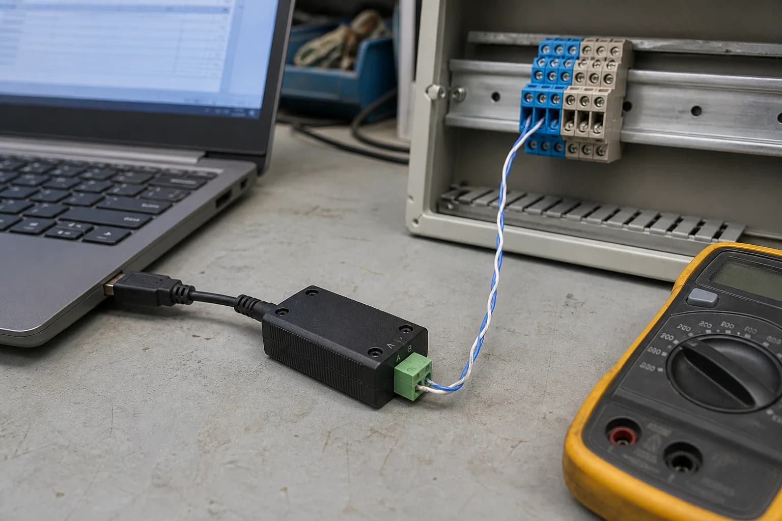
Prove the RS-485 segment with a known test adapter before debugging application firmware.
Troubleshooting order that saves time
When the values look wrong, I work from the bottom up:
- Power and common reference.
- A/B polarity and termination.
- UART pins and transceiver direction control.
- Baud rate, parity, stop bits, and slave ID.
- Function code and zero-based address.
- Register width, scaling, and byte/word order.
- Task timing, timeout, and reconnect logic.
Do not change five settings at once. A USB-RS-485 adapter and a simple Modbus test tool are often worth more than another hour of guessing in firmware.
Closing thoughts
ESP32 makes a capable IIoT edge node because it is inexpensive, connected, and pleasant to iterate with. The reliable part comes from the boundaries: let the PLC keep deterministic machine logic, treat the register map as a contract, isolate the control task from the network, and make stale data visible.
That approach scales better than a demo that polls a register in loop() and toggles an output whenever a packet happens to arrive.
References
Share
Keep exploring
Read next
Related articles
5G IoT with ESP32: Connect NB-IoT & LTE-M from Modem to MQTT
A practical ESP32 guide to integrating an NB-IoT/LTE-M modem: choose the network, power it safely, wire UART, use TinyGSM and send first telemetry.
Real-Time Operating System (RTOS): FreeRTOS on ESP32
A beginner-friendly guide to using FreeRTOS on ESP32 for multitasking firmware with tasks, queues, notifications, mutexes, and practical debugging habits.
ESP32 Memory Management Deep Dive: SRAM, PSRAM, Heap and FreeRTOS Stacks
A practical ESP32 memory guide covering SRAM layout, PSRAM usage, heap fragmentation, RTOS task stacks, and small optimization tricks that are useful in real firmware.