

nRF52840 BLE Wearables: How to Build a Wearable Device
A practical guide to building nRF52840 BLE wearables with open-source references, Zephyr, compact GATT design, sleep/wake states, and real power measurements.
Share
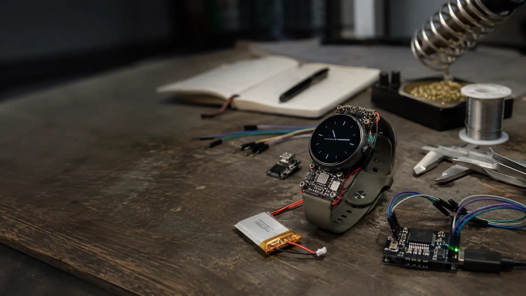
If you want to build a small wearable with BLE that runs for days or weeks on a battery, the nRF52840 is a very comfortable place to start. It is not the most powerful Nordic chip, but it has what a wearable needs: reliable BLE, plenty of peripherals, USB, crypto, and enough headroom for serious firmware.
I am approaching this as a practical build guide. I will not promise “a year on one battery” without knowing your display, sensors, and connection duty cycle. The goal is a prototype you can measure, debug, and improve one decision at a time.
Start with an open project
Before drawing a custom PCB, I like to read a project that has already met the hard problems. Three good repositories are:
- K-Watch, an open hardware and firmware smartwatch based on nRF52840 and Zephyr, with a memory-in-pixel display, sensors, haptics, and power management.
- InkTime, an nRF52840 low-power smartwatch project with its own PCB and enclosure.
- MakerWatch, a maker-oriented smartwatch using an nRF52840-based module, IMU, and battery-management hardware.
ZSWatch is also useful for studying Zephyr architecture, apps, and the companion app. Current ZSWatch versions use nRF5340, though, so I treat it as an architecture reference rather than a drop-in nRF52840 design.
The shared lesson is simple: a wearable is not just “MCU + BLE + battery.” The display, sensors, PMIC, firmware, and wake model have to work as one system.
What kind of wearable fits nRF52840?
The nRF52840 gives you a 64 MHz Cortex-M4F, 256 KB RAM, 1 MB flash, BLE 5, and USB. That is enough for:
- a motion, step, or activity band;
- a BLE tag with a button, buzzer, and environmental sensor;
- a simple watch with an e-paper or memory-in-pixel display;
- a BLE remote, safety button, or phone-connected telemetry device.
It would not be my first choice for audio streaming, a heavy color UI, or complex biosignal processing. For those, an nRF5340 or a roomier SoC will make life easier.
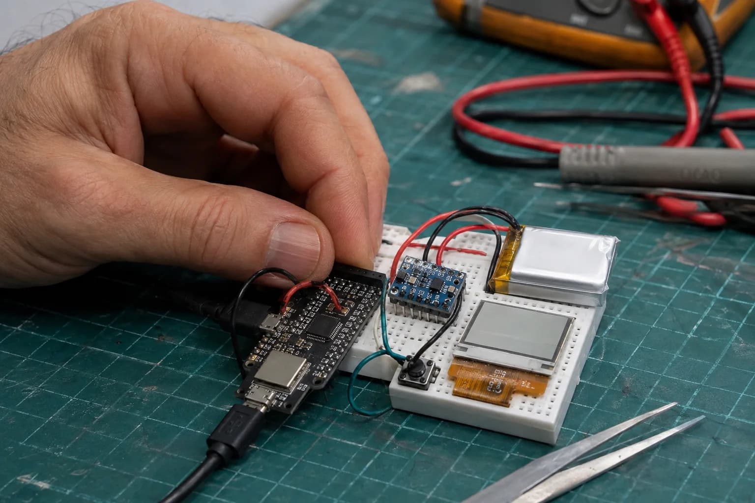
Keep the first prototype exposed: visible wires and separate modules make debugging much easier.
A minimum hardware architecture
A debug-friendly wearable prototype can start with these blocks:
| Block | Practical choice | What to check |
|---|---|---|
| MCU + BLE | nRF52840 module or DK | antenna, flash, SWD, and board sleep current |
| Motion | I2C/SPI IMU with interrupt | motion wake and suspended current |
| Display | e-paper, MIP, or small OLED | refresh current; avoid keeping OLED on |
| Power | Li-Po plus charger/PMIC | power path, protection, and quiescent current |
| Input | button, touch, or gesture | debounce and wake source |
For the first prototype, I prefer a module with a known antenna and separate sensor breakouts. It is larger than the final product, but it lets you separate firmware, power, and RF problems. Once the behavior is stable, move to a four-layer PCB with a proper ground plane and an antenna layout that follows the module guidance.
Measure the whole board. A development board with a regulator, LED, and USB-UART can consume more than a bare nRF52840 module. Do not use a DK measurement to promise final-product battery life.
BLE: keep GATT small and versioned
BLE is not an invisible serial port. A wearable should expose a clear GATT layout, for example:
Device Information: firmware version and hardware revision;Sensor Data: a Notify characteristic for measurements;Control: a Write characteristic for configuration;Battery: Read/Notify for battery percentage and charging state.
Keep packets short and versioned. For sensor data, a fixed binary packet is often easier to control than JSON:
struct sensor_packet {
    uint8_t version;
    uint8_t flags;
    int16_t ax_mg;
    int16_t ay_mg;
    int16_t az_mg;
    uint16_t sequence;
};
sequence lets the app detect lost packets; flags gives you room to extend the format without breaking an older client. If you stream samples, consider batching a few samples and notifying once instead of waking the radio for every sample.
Zephyr and the energy lifecycle
For a wearable, I like Zephyr's event-driven model: the system sleeps when there is no work, then wakes on a timer, GPIO, sensor interrupt, or BLE event. Avoid a continuously running while loop that reads sensors. It is easy to write and often where battery gets burned unnoticed.
A basic loop looks like this:
- The IMU runs in low-power mode and raises an interrupt on motion.
- The nRF52840 wakes and reads a burst of samples over I2C/SPI.
- Firmware updates a buffer or step state.
- BLE notifies on the chosen schedule, then the system sleeps again.
- The display refreshes only after a data change or button press.
In Zephyr, keep board configuration, GPIO interrupts, I2C, and BLE settings in device tree and Kconfig instead of scattering hard-coded values through the application. Start from the official BLE peripheral sample, then add one peripheral at a time and measure after each change.
Low power is really about duty cycle
There is no single “nRF52840 current consumption” number. Your battery sees the combination of states:
I_avg ≈ (I_sleep × t_sleep + I_sensor × t_sensor + I_radio × t_radio + I_display × t_display) / T
The practical improvements are familiar:
- increase the advertising interval when the device does not need constant discovery;
- choose a sensible connection interval instead of the fastest one by default;
- turn off unused regulators and sensors;
- batch data before sending it;
- debounce buttons with a timer instead of a busy-wait;
- let the display sleep and redraw only what changes when its driver allows it.
Do not optimize by intuition. Measure advertising, connected idle, sensor sampling, notifications, and display refresh as separate test cases.
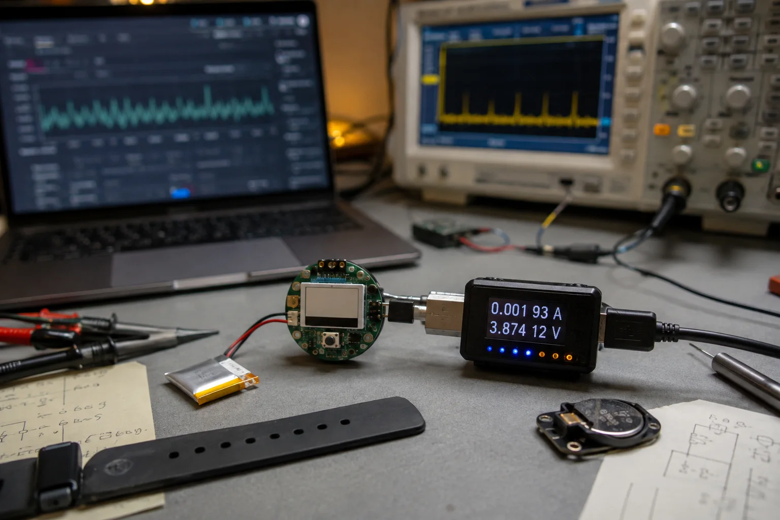
A good sleep-current number in a datasheet says little until the display, sensors, and BLE are measured together.
Measure on the bench, then wear it
A cheap USB power meter is a useful starting point, but it usually misses short radio peaks. When you need more detail, use a power analyzer or an oscilloscope with a suitable shunt. Record more than average milliamps:
- TX and display-refresh peaks;
- time spent in each state;
- reconnect count;
- current when charging starts and stops;
- runtime with the actual release firmware.
Then test it on a wrist: walk, type, keep the phone in a pocket, lose the connection, and walk back into range. A good wearable behaves predictably when the user is not sitting still on a lab bench.
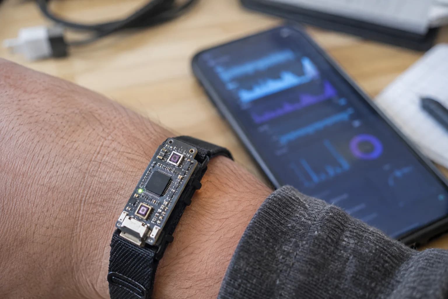
Do not test only on the bench. Wrist position, movement, and distance to the phone all affect the experience.
A lower-risk prototype path
I would split the work into four milestones:
- BLE hello world: advertise, connect, and expose one notifying characteristic.
- Sensor loop: add the IMU, interrupt handling, and a packet with a sequence number.
- Battery loop: add charging, battery measurement, sleep/wake, and current measurements.
- Wearable loop: add the display and input, enclosure, on-body RF tests, and runtime tests.
At every milestone, save the firmware, configuration, wiring, and measurements. A small table in the repository is usually more useful than the words “low power” in a README.
What would I choose?
For learning BLE and building a simple sensor wearable or watch, I would start with an nRF52840 DK or a module with clear USB/SWD support, then study K-Watch and InkTime for system-level decisions. Use Zephyr for the firmware and a small GATT client on the phone for early checks.
Once the prototype works, the important work is not adding more features. It is removing unnecessary wakeups, checking the antenna on the final PCB, and measuring the complete power budget again. That is when a BLE demo starts becoming a wearable you can actually use.
References and open projects
Share
Keep exploring
Read next
Related articles
Real-Time Operating System (RTOS): FreeRTOS on ESP32
A beginner-friendly guide to using FreeRTOS on ESP32 for multitasking firmware with tasks, queues, notifications, mutexes, and practical debugging habits.
Over-The-Air (OTA) Firmware Updates: Design & Implementation
A practical guide to designing safe OTA firmware updates for ESP32 and STM32, covering partitions, signed images, rollback, rollout control, and delta updates.
RISC-V Embedded Development: Getting Started with ESP32-P4
A practical ESP32-P4 RISC-V guide: install ESP-IDF, select the esp32p4 target, build a first project, flash over USB, and understand the dual-core architecture.