

RISC-V Embedded Development: Getting Started with ESP32-P4
A practical ESP32-P4 RISC-V guide: install ESP-IDF, select the esp32p4 target, build a first project, flash over USB, and understand the dual-core architecture.
Share
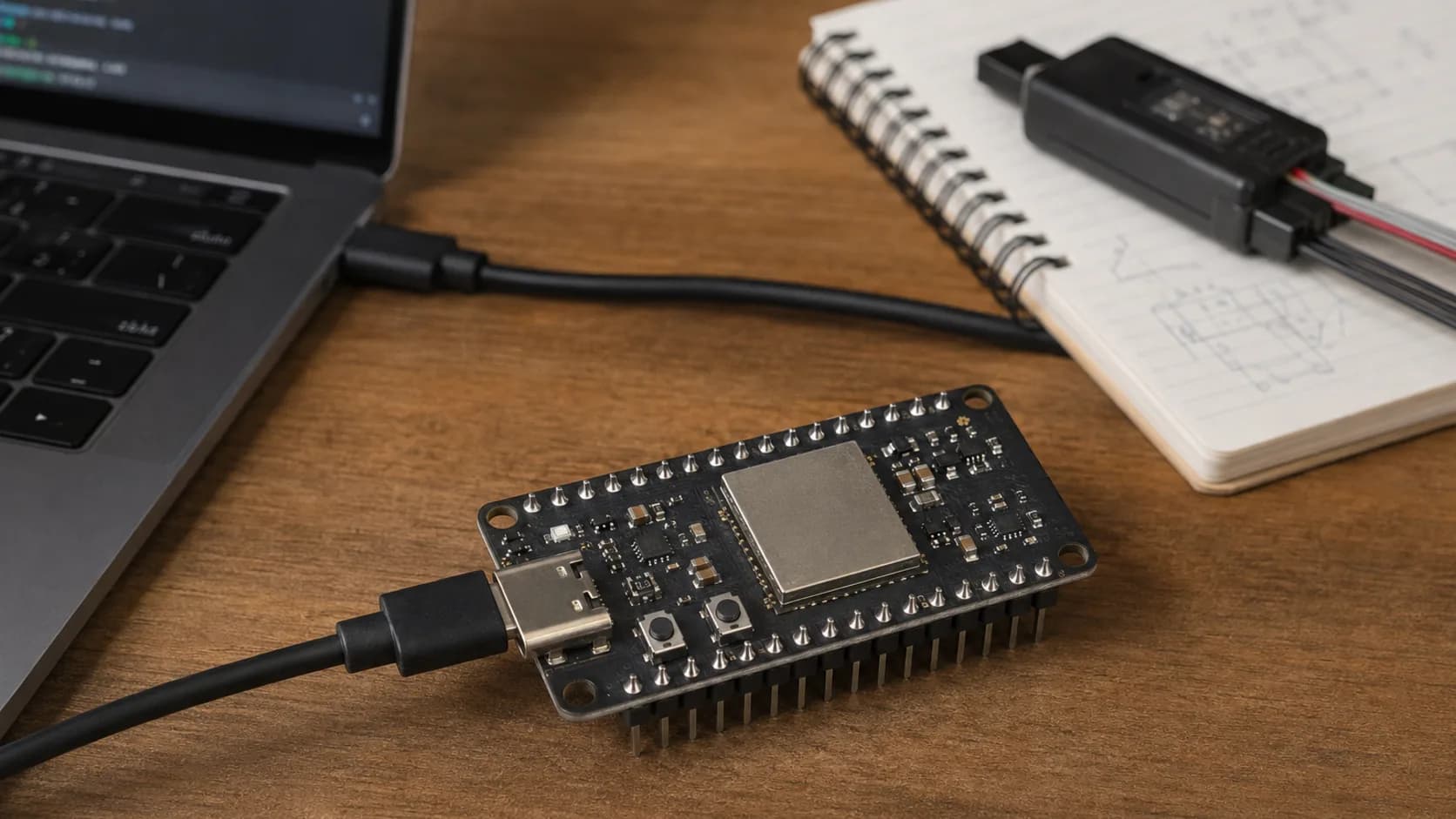
RISC-V can sound abstract until you have a board on your desk and a firmware log in front of you. With ESP32-P4, the interesting part is not just the CPU instruction set. It is the combination of a RISC-V high-performance system, a low-power subsystem, fast peripherals, and an ESP-IDF workflow that still feels familiar if you have used another ESP32.
One detail is worth putting up front: ESP32-P4 does not include built-in Wi-Fi or Bluetooth. If your project needs wireless connectivity, you pair it with an external wireless SoC such as ESP32-C5 or ESP32-C6. That is not a limitation to hide; it is part of the architecture and helps you choose the board correctly.
In this guide, I will take the shortest useful path: understand the chip, install the right ESP-IDF tools, build hello_world, flash it, and then make sense of the two RISC-V systems before moving to a real application.
What makes ESP32-P4 different?
ESP32-P4 has two RISC-V systems:
- The HP system contains two high-performance RISC-V cores running up to 400 MHz.
- The LP system contains a separate low-power RISC-V core running up to 40 MHz.
The chip also brings a rich peripheral set, including USB, MIPI, SDIO, Ethernet, image and voice processing features, floating-point support, and security hardware. That makes it a good fit for cameras, displays, HMI devices, gateways, and local AI or signal-processing work.
The practical takeaway is simpler: do not treat ESP32-P4 as a faster drop-in replacement for an ESP32-C3. Start by checking which subsystem owns the peripheral you need, which core runs the code, and whether the development board exposes the pins and USB path you expect.
Hardware and software checklist
You need:
- An ESP32-P4 development board such as ESP32-P4-Function-EV-Board or ESP32-P4-EYE.
- A USB cable that matches the connector on your board.
- A Windows, Linux, or macOS computer.
- ESP-IDF and the ESP32-P4 toolchain.
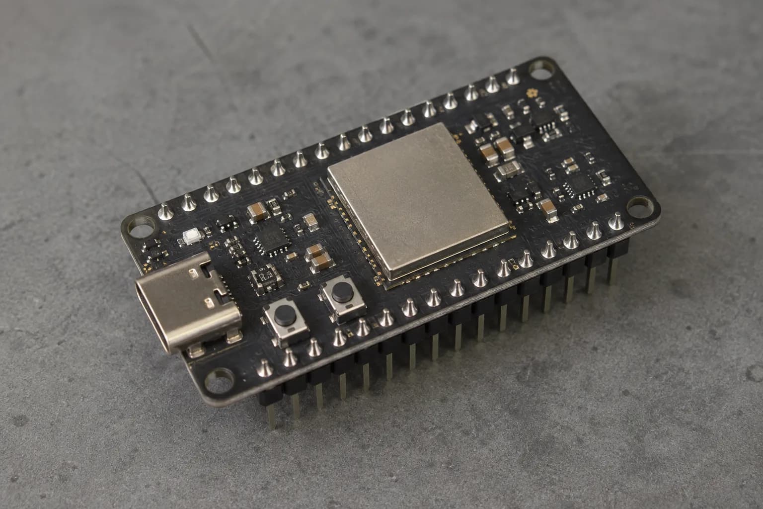
Start by identifying the real board layout: one USB-C connector, two buttons, mounting holes, and the headers you can actually use.
Do not assume every P4 board has the same connector or serial arrangement. Some boards expose USB directly, while others include a USB-to-UART bridge. The pinout, boot buttons, power input, and available camera/display connectors are board-level details, not properties you can safely infer from the chip name.
Install ESP-IDF for the P4 target
Espressif's current installation flow uses the ESP-IDF Installation Manager, but the important part for this project is that the esp32p4 tools are installed. After opening an activated ESP-IDF terminal, verify the environment:
idf.py --version
Create a project from the official example:
cd ~/esp
cp -r $IDF_PATH/examples/get-started/hello_world esp32-p4-hello
cd esp32-p4-hello
idf.py set-target esp32p4
On Windows PowerShell, use the ESP-IDF terminal supplied by Espressif and copy the example with the equivalent PowerShell command. The key command is still:
idf.py set-target esp32p4
This target selection matters. It chooses the correct compiler, linker settings, SoC headers, bootloader configuration, and supported component options. If you skip it, the project can accidentally remain configured for another ESP32 family.
Build, flash, and monitor
Build first so errors are easy to separate from connection problems:
idf.py build
Connect the board and flash it:
idf.py -p PORT flash
Then open the serial monitor:
idf.py -p PORT monitor
Or combine the last two steps:
idf.py -p PORT flash monitor
If the board uses the ESP32-P4 USB peripheral, you may be able to flash without an external USB-to-UART chip. The first connection can require a manual download-mode sequence: hold BOOT, press RESET, then release BOOT. The exact port name depends on your operating system and board.
I recommend saving the first successful output. It gives you a known-good baseline before you change clocks, FreeRTOS tasks, USB settings, or peripheral drivers.
A first RISC-V experiment
The first experiment does not need assembly. Put a small piece of work in a FreeRTOS task, print the core ID, and observe where it runs:
#include "freertos/FreeRTOS.h"
#include "freertos/task.h"
#include "esp_log.h"

static const char *TAG = "riscv-demo";

static void worker_task(void *arg)
{
    while (1) {
        ESP_LOGI(TAG, "running on core %d", xPortGetCoreID());
        vTaskDelay(pdMS_TO_TICKS(1000));
    }
}

void app_main(void)
{
    xTaskCreate(worker_task, "worker", 4096, NULL, 5, NULL);
}
The value of this exercise is not the log itself. It is learning to verify assumptions. On a dual-core system, task affinity and interrupt placement can affect latency. Measure before you decide that a task belongs on one core or the other.
How to think about HP and LP work
For a first application, keep the split practical:
| Work | Good starting place | Why |
|---|---|---|
| UI, camera pipeline, networking, heavy transforms | HP system | More compute and richer high-speed peripherals |
| Periodic housekeeping or low-power monitoring | LP system, when the board/SDK path supports it | Lower-power work can be isolated from the main application |
| Safety-critical timing | Whichever subsystem owns the peripheral, verified with measurement | Peripheral ownership matters more than labels |
The LP core is not an automatic battery-saving button. Your board, power tree, wake-up source, SDK support, and application state all matter. Start with a working HP application, then move one small responsibility to the LP side and measure current, wake time, and data handoff.
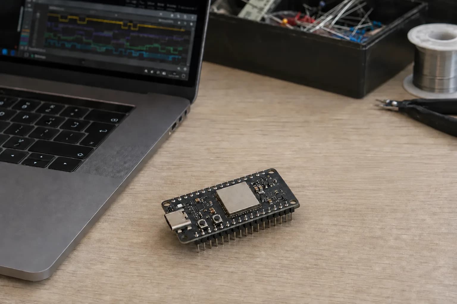
The dual-core design becomes useful when you measure the work instead of guessing which core is busy.
For debugging, log timestamps, core IDs, queue latency, and buffer ownership. If a camera or display path drops frames, first check whether a task is blocking, a buffer is copied too often, or an interrupt is starved. RISC-V gives you a clean architecture; it does not remove normal embedded systems trade-offs.
Where USB fits
USB is especially useful on ESP32-P4 because it can provide a direct path for flashing and serial/JTAG workflows, depending on the board design. Espressif documents the USB D+ and D- signals for the P4 and notes that some boards instead use a USB-to-UART bridge.
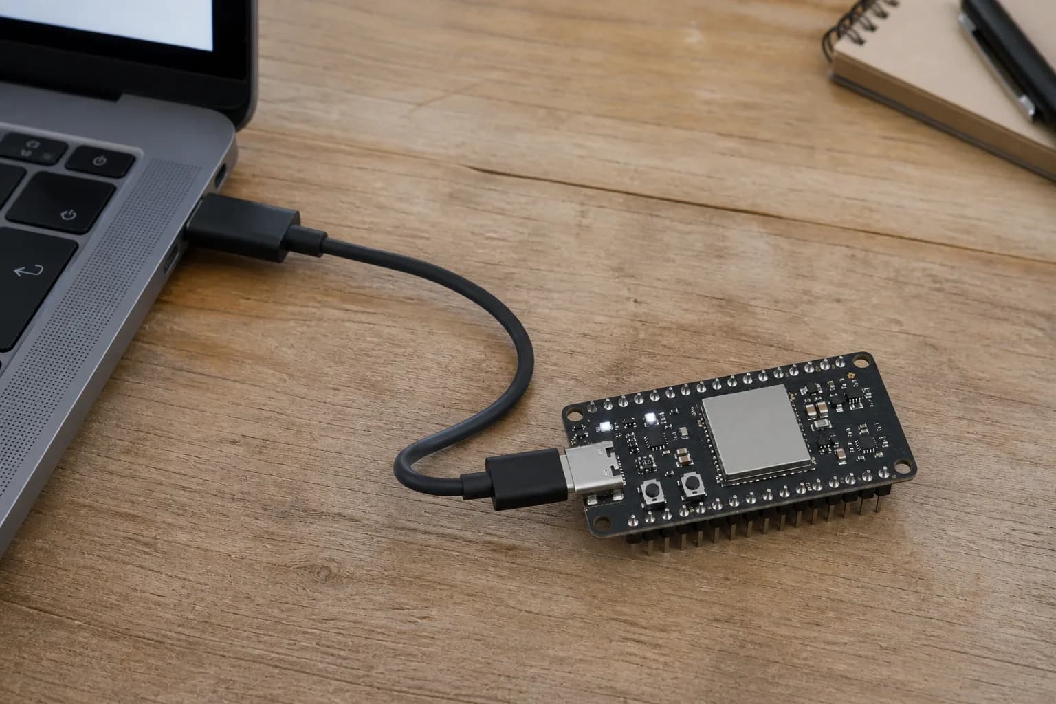
Flashing over the board's supported USB path is a simple milestone before adding displays, cameras, or a wireless companion chip.
When a flash attempt fails, check these in order:
- Is the selected target really
esp32p4? - Does the board use native USB or a bridge chip?
- Is the correct port selected and free from another monitor process?
- Did the board enter download mode?
- Are the USB data lines and cable suitable for data, not charge-only?
This checklist catches more problems than changing baud rates at random.
A sensible next project
Once hello_world works, choose one vertical slice instead of enabling every peripheral at once. For example:
- Read a sensor over I2C.
- Render one small status screen.
- Stream one camera frame format.
- Send one Ethernet message.
- Pair the P4 with an external ESP32-C6 for wireless connectivity.
Keep the first version observable: serial logs, a heartbeat LED, a measured frame rate, or a counter visible on the display. A small, measurable milestone tells you whether a failure comes from the board, the driver, the scheduler, or the application.
Common mistakes to avoid
- Treating ESP32-P4 as if it had native Wi-Fi or Bluetooth.
- Using a generic ESP32 example without checking its supported-target table.
- Assuming all P4 development boards expose the same USB connector and boot flow.
- Moving work to the LP core before understanding wake-up and data handoff costs.
- Debugging a timing issue with logs so heavy that the logs create the timing issue.
Wrap-up
ESP32-P4 is a friendly way to get practical with RISC-V because the toolchain, project commands, and ESP-IDF APIs give you a familiar starting point. The new parts are the dual-core HP system, the LP subsystem, the richer peripheral set, and the explicit decision to use an external wireless companion when needed.
My advice is to make the first project intentionally unexciting: set esp32p4, build the official example, flash it over the board's real USB path, and record a clean serial log. Once that baseline is solid, the more ambitious camera, display, Ethernet, and multi-chip designs become much easier to reason about.
References
Share
Keep exploring
Read next
Related articles
Real-Time Operating System (RTOS): FreeRTOS on ESP32
A beginner-friendly guide to using FreeRTOS on ESP32 for multitasking firmware with tasks, queues, notifications, mutexes, and practical debugging habits.
ESP32 Memory Management Deep Dive: SRAM, PSRAM, Heap and FreeRTOS Stacks
A practical ESP32 memory guide covering SRAM layout, PSRAM usage, heap fragmentation, RTOS task stacks, and small optimization tricks that are useful in real firmware.
18 Common ESP32 Errors – Part 2: Critical Errors
How I read ESP32 backtraces and troubleshoot crashes, watchdogs, heap, stack, FreeRTOS, Wi-Fi, ADC, deep sleep, and OTA with a practical runtime checklist.