

The Open Book - Open-Source Raspberry Pi Pico E-Reader PCB
Author: Joey Castillo (Oddly Specific Objects)
Open-source The Open Book PCB for a Raspberry Pi Pico e-reader with 4.2-inch e-paper display, AAA battery power, and hand-solderable parts.
Main components
Share
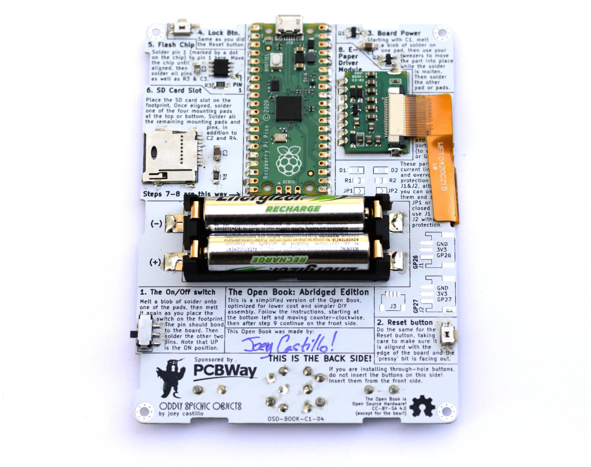
PCB photos
Quick Specs
- Main IC
- Raspberry Pi Pico
- Status
- Concept
What it is
An open-source e-reader built around a Raspberry Pi Pico and a 4.2" grayscale e-paper display, designed to be simple enough that anyone with a soldering iron can build and understand one. This "reboot" version replaces the project's original design with one optimized for low part count and easy hand assembly, running on two AAA batteries rather than a rechargeable LiPo cell.
Main components
- Raspberry Pi Pico (main microcontroller, with its own USB port for programming)
- GDEW042T2 4.2" grayscale e-paper panel (deliberately not the tri-color variant, which refreshes far more slowly)
- A separate Castellated E-Paper Driver module, connected via a flex cable
- GD25Q16C SPI flash chip, holding Unicode font data from GNU Unifont
- MEM2075 microSD card slot for book files
- Seven front navigation buttons plus dedicated Reset and Lock buttons
- Keystone 1022 dual-AAA battery holder with a power switch that disables all circuits for long standby life
What you can use it for
- Building a fully open e-reader you can understand down to the schematic level
- A reference design for a hand-solderable board (roughly 7 through-hole and 14 SMD 1206 parts) driving e-paper through a separate castellated driver module
- A starting point for your own reader hardware — the project explicitly invites forking and tweaking
Notes before use
- Nastrotek has not independently fabricated or tested this board yet.
- This is a mature, widely-built project (8,000+ GitHub stars); the current design is a Pi Pico-based reboot, with the earlier version archived in the repository's
originalbranch. - You need two custom boards fabricated: the Open Book Main Board (bare PCB) and the Castellated E-Paper Driver (best ordered as a PCBA job — pre-assembled — since it uses fine-pitch parts).
- Firmware, called "libros," lives in a separate repository and is not covered by this resource.
- Licensed CC-BY-SA 4.0 — the board's own silkscreen carries the license mark.
Source / reference
Original hardware design by Joey Castillo / Oddly Specific Objects, documentation at oddlyspecificobjects.com.
The design, documentation, and images shown here are attributed to Joey Castillo / Oddly Specific Objects under CC BY-SA 4.0. Any resized or cropped versions remain under the same license.
How to evaluate this board
Read this resource as a starting point for review, not as a board you should manufacture blindly. Open the schematic first and identify the power input, regulator path, MCU or main controller, external connectors, programming interface, and any sensor or display interfaces. Once the functional blocks are clear, it becomes much easier to decide whether the design matches your project.
For this board, the layout review is mostly about assembly and connector fit. Check the Pico headers, e-paper flex orientation, microSD footprint, front-button spacing, reset/lock buttons, battery-holder clearance, and whether the two-board stack leaves enough room for the display cable. I would also inspect the SPI flash routing and add my own test notes before changing the enclosure.
Before reusing the files
- Check the license and original author notes.
- Confirm voltage levels before connecting external modules.
- Verify connector pinout against your cables and sensors.
- Review BOM availability before ordering PCBs.
- Export fresh Gerbers from the design tool if you modify anything.
- Treat untested designs as references until you have fabricated and measured them.
Good use cases
This kind of resource is useful when you want to study a real open-source hardware design, borrow part of a circuit, or compare layout decisions before creating your own board. Even if you do not fabricate the PCB directly, the schematic can still be valuable as a reference for power design, connector planning, enclosure constraints, or firmware bring-up.
For a small product prototype, the best workflow is to reuse ideas carefully: copy the principle, not the entire board without context. Mark what you changed, keep notes on assumptions, and add measurement points so the first fabricated board can teach you something useful.
Related reading
Download Resource
File details & download
- File type
- Design File
- Version
- Not specified
- File size
- Not specified
- Author
- Joey Castillo (Oddly Specific Objects)
- Original source
- Open original source · github.com
- License
- Not verified
- Commercial use
- Not verified
- Last checked / updated
- Jul 31, 2026
- Tested by Nastrotek
- Not verified
The license has not been verified. Do not assume this resource is free to reuse, redistribute, or use commercially.
Share
Keep exploring
Read next
Related articles
GPT-6 Astra and the Future of PCB Design: Speed Up or Replace Engineers?
How far can GPT-6 Astra go in KiCad? An independent look at the demo, EEBench, open-source tools, and why routing a board is not the same as making it production-ready.
Net Classes and Trace Width: When Should a PCB Trace Be Wider?
A practical guide to PCB net classes and trace width for small boards: signal traces, 3V3, 5V, battery paths, ground, power vias, and a pre-Gerber checklist.
PCB Ground Planes: GND Is More Than a Net Name
A practical guide to PCB ground planes, return current, GND layout mistakes, stitching vias, decoupling paths, and copper pour checks.