

Choosing Capacitors for Electronics: Simple Part, Easy Mistake
A beginner guide to choosing capacitors for circuits: capacitance, voltage rating, decoupling, ceramic types, DC bias, and ESP32 values.
Share
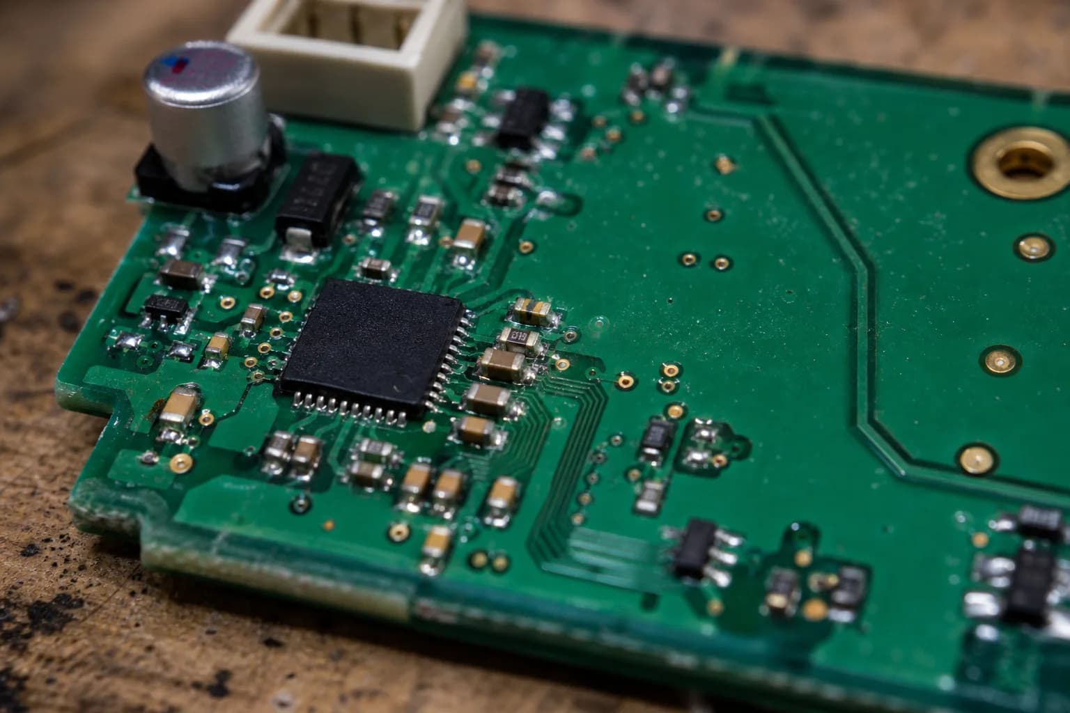
Capacitors are everywhere on a PCB. At first they look like simple parts: choose a capacitance, choose a voltage rating, place them on the schematic, and move on. In practice, a poorly chosen capacitor can cause random resets, noisy rails, flickering displays, audio noise, or shorter component life.
This post is a practical beginner guide. If you are building an ESP32 board, a sensor module, a small display product, or a 3.3V-5V power rail, these are the capacitor choices I would think through first. You do not need to memorize every formula to get started. A few habits already prevent many painful PCB problems.
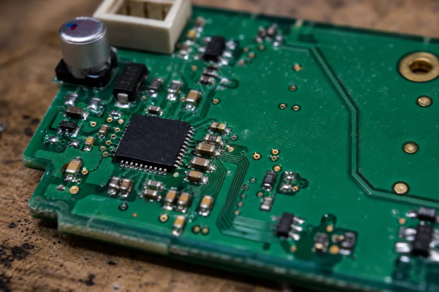
SMD capacitors are often placed close to ICs and power sections so they can support the rail right where the circuit needs it.
What Capacitance Really Tells You
Capacitance tells you how much electric charge a capacitor can store. In small electronics, you will usually see:
pF: picofarads, common in oscillators, RF, and fast signal paths.nF: nanofarads, very common for noise filtering.uF: microfarads, often used around power rails and loads that draw changing current.
As a useful mental model, small capacitors are better at responding to fast noise, while larger capacitors help when the load needs a short burst of energy. That is why a PCB often uses several values together, such as a 100nF capacitor close to an IC and a 1uF or 10uF capacitor nearby on the same rail.
A common beginner mistake is assuming bigger is always better. It is not that simple. The right value depends on the location, the load, the noise frequency, the IC requirements, and the PCB layout.
Leave Margin on Voltage Rating
The voltage rating is the maximum voltage the capacitor is designed to handle. For example, 10uF / 6.3V, 10uF / 16V, and 10uF / 25V all have the same nominal capacitance, but they tolerate different voltages.
If your rail is 5V, do not use a capacitor rated below 5V. More importantly, do not choose a rating that sits right on the edge. Power rails can see short spikes when USB is plugged in, loads switch, motors start, relays move, or Wi-Fi current peaks.
A practical starting point:
| Rail voltage | Capacitor voltage to consider |
|---|---|
| 3.3V | 6.3V, 10V, or 16V |
| 5V | 10V, 16V, or 25V |
| 12V | 25V or higher |
For most 3.3V-5V boards, 10V or 16V capacitors are a comfortable choice. If you want to simplify the BOM, using 16V capacitors in many positions can be convenient, as long as package size, price, and availability still make sense.
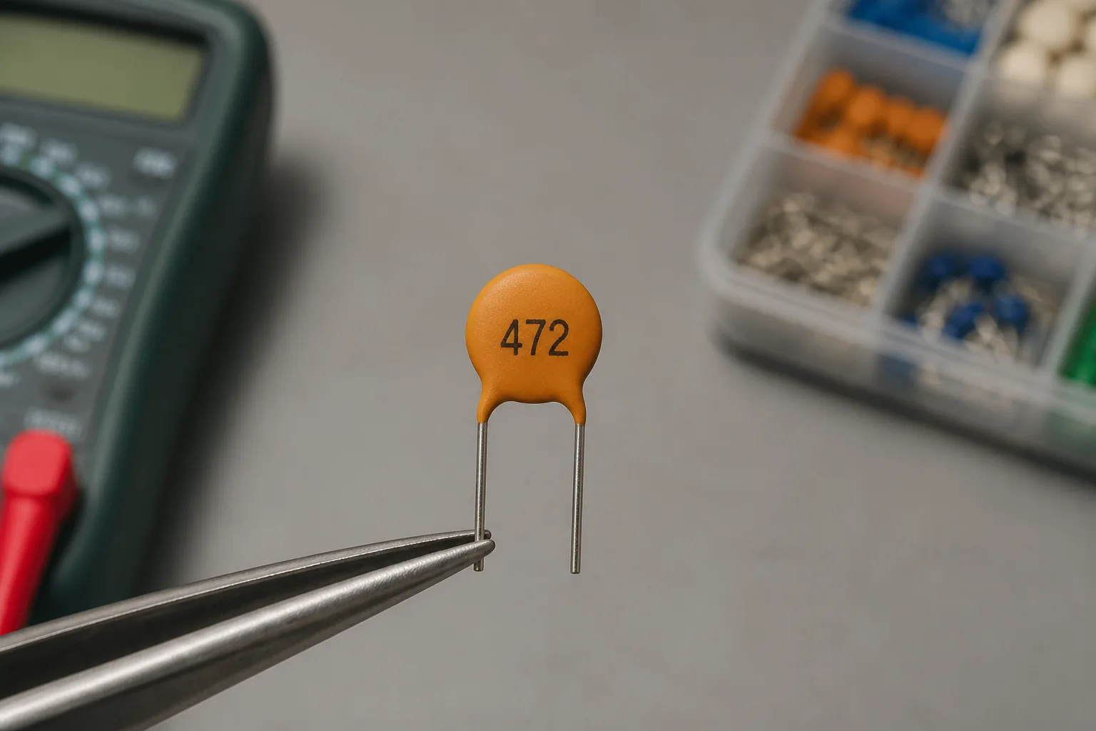
The value marking is only part of the story; voltage rating and capacitor type still matter when choosing the part.
Why 100nF Capacitors Sit Beside ICs
When an IC switches internally, it may need a very fast pulse of current. If that current has to travel from the regulator, through a long trace, and then into the IC power pin, the voltage at the IC can bounce.
A 100nF capacitor close to the power pin acts like a tiny local reserve. When the IC suddenly needs current, the capacitor helps for a very short moment. When fast noise appears on the rail, the capacitor also gives that noise a short return path to ground.
The practical rule is:
- Give each digital IC at least one
100nFcapacitor near its power pin. - Give an ESP32 or MCU additional bulk support such as
1uF,4.7uF, or10uF. - Place the capacitor close to the actual power pin, not merely somewhere on the schematic.
That last point matters a lot. A 100nF capacitor several centimeters away from the IC may be far less effective than the same capacitor placed right beside VDD with a short ground return.
A Decoupling Capacitor Is Not a DC Short
Beginners sometimes see VCC -> capacitor -> GND on a schematic and wonder whether it shorts power to ground.
It does not. The two plates inside the capacitor are separated by a dielectric, so under steady DC conditions the capacitor does not create a direct short. But when voltage changes quickly, the capacitor can charge or discharge, helping the rail settle.
Think of it as a small local reservoir:
- When the load needs a fast burst of current, the capacitor supplies part of it.
- When a noise spike appears, the capacitor absorbs part of that energy.
- When the rail settles, the capacitor charges back to the rail voltage.
That is why decoupling capacitors appear around MCUs, regulators, sensors, displays, amplifiers, and input connectors.
Where Power Noise Comes From
On a small board, noise is not always caused by a bad regulator. It often comes from the load itself:
- An ESP32 enabling Wi-Fi or Bluetooth.
- A display changing backlight brightness.
- An audio amplifier drawing current with volume peaks.
- A switching DC-DC converter.
- Motors, relays, or high-power LEDs switching on and off.
- Long power wires or a weak USB supply.
When a 3.3V rail dips for only a very short time, a multimeter may show nothing unusual. The ESP32 may still reset, a sensor may misread, or audio may become noisy. Good capacitor choices and placement help a lot, though an oscilloscope is still the best way to confirm what is happening.
Ceramic or Electrolytic?
No capacitor type is best everywhere. Each one has a job.
Ceramic capacitors use ceramic material as the dielectric between their electrodes. They are usually small, low-ESR, and good at high-frequency decoupling. Common values include 100nF, 1uF, 4.7uF, and 10uF.
Electrolytic capacitors use an electrolyte and an oxide layer to form the dielectric. This structure provides larger capacitance at low cost, so they are common near power inputs, larger loads, amplifiers, motors, or places that need tens or hundreds of microfarads. Most electrolytic capacitors are polarized, so installing them backward can damage them.
A very common pairing is:
100nF ceramic + 10uF ceramic/electrolytic
The 100nF capacitor handles faster noise, while the 10uF capacitor supports slower rail movement or larger load changes.
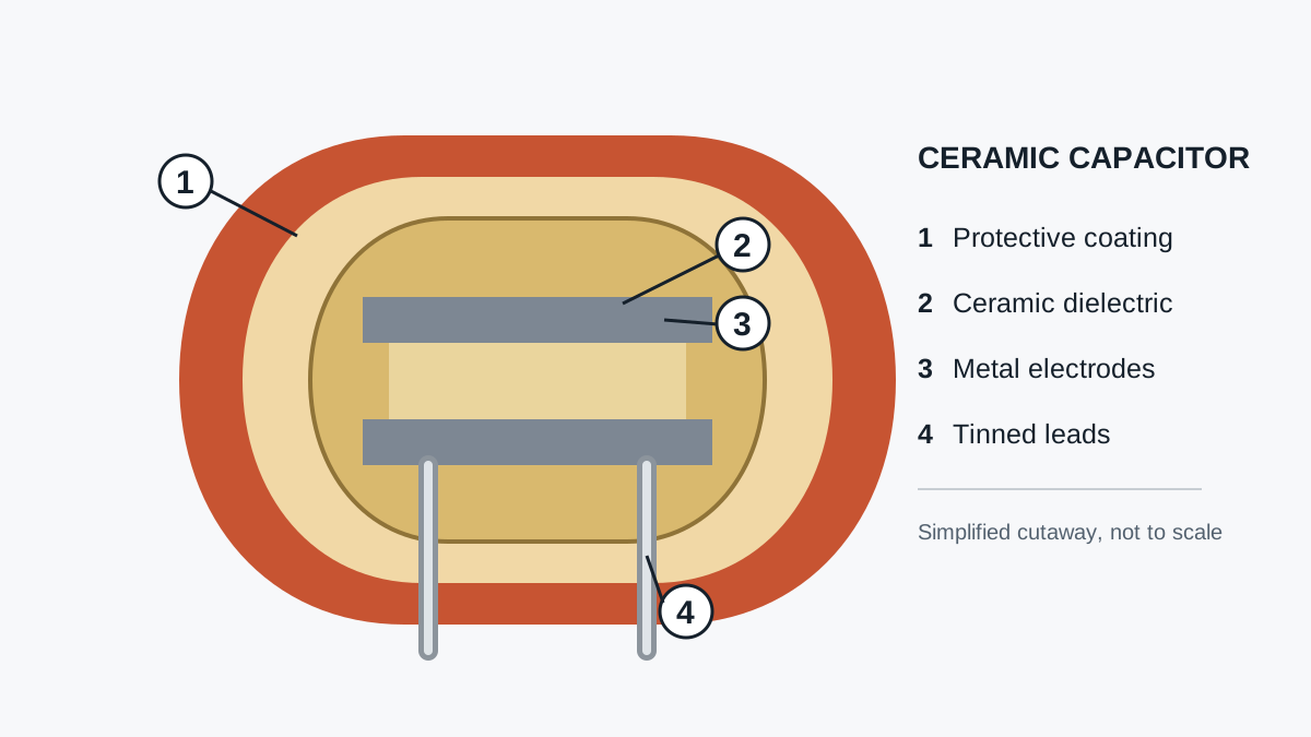
A ceramic capacitor has a dielectric layer between conductive regions; that material has a big influence on how the capacitor behaves.
One Catch With Larger Ceramic Capacitors
MLCC ceramic capacitors do not always keep their marked capacitance once they are operating in a real circuit. With some high-value ceramics, the effective capacitance can drop significantly when DC voltage is applied. This is usually called DC bias.
For example, a 10uF / 6.3V capacitor on a 5V rail may provide much less than 10uF in practice, especially in small packages such as 0603 or 0805.
That is why 10uF / 10V or 10uF / 16V often feels safer than 10uF / 6.3V on a 5V rail. For serious designs, check the datasheet of the exact capacitor series, because two parts with the same printed value can behave differently under DC bias.
Quick Choices for ESP32 3.3V-5V Boards
If you are designing a basic ESP32 PCB with USB 5V, a 3.3V regulator, sensors, and a few support ICs, this is a practical starting point:
| Position | Practical starting value |
|---|---|
| Each digital IC | 100nF ceramic |
| ESP32 / MCU | 100nF + 10uF |
| LDO input | 1uF-10uF, per datasheet |
| LDO output | 1uF-10uF, per datasheet |
| USB 5V input | 10uF-47uF + 100nF |
| Sensor | 100nF + 1uF |
| Amplifier or high-current load | 100nF + 10uF-100uF |
For voltage rating:
- 3.3V rail: prefer
10Vor16V. - 5V rail: prefer
10Vor16V;25Vis also fine if size and cost are acceptable. - To simplify the BOM: using many
16Vceramic capacitors is often convenient.
Treat this as a starting point, not a fixed rule. The IC datasheet and the physical PCB layout still decide the final answer.
A Small Pre-PCB Checklist
Before sending a board out, I like to ask:
- Does every digital IC have a nearby
100nFcapacitor? - Do the LDO input and output capacitors match the datasheet requirements?
- Are capacitors on the 5V rail rated with enough voltage margin?
- Are polarized capacitors clearly marked on the silkscreen?
- Do decoupling capacitors have a short return path to ground?
- Is the bulk capacitor close to the power entry point or the high-current load?
- Am I using a large ceramic capacitor too close to its rated voltage?
This checklist is small, but it catches many mistakes before the PCB is manufactured.
Conclusion
When choosing capacitors, start with three questions: where is the capacitor placed, is it handling fast noise or larger load changes, and what voltage rail is it connected to?
For many ESP32-style 3.3V-5V boards, 100nF + 1uF + 10uF is a very practical starting set. Leave voltage margin, place capacitors close to the circuits they support, and check the datasheet whenever an IC has specific requirements.
Capacitors are small parts, but when they are chosen and placed well, the whole board feels calmer: cleaner rails, easier debugging, and a better chance that the first prototype behaves.
Thanks for reading to the end. I hope these notes make the next capacitor choice feel a little less mysterious.
References
These sources are useful background material for checking terminology, limits, and engineering recommendations before applying the notes to a real prototype.
- Murata Ceramic Capacitor FAQ: DC bias characteristics
- Texas Instruments Precision Labs: Decoupling capacitors
Image provenance
The PCB photograph, the 472 capacitor photograph, and the cutaway diagram were created specifically for Nastrotek. The diagram is a simplified conceptual illustration and does not copy a manufacturer's technical-artwork layout.
Related reading
Share
Keep exploring
Read next
Related articles
Net Classes and Trace Width: When Should a PCB Trace Be Wider?
A practical guide to PCB net classes and trace width for small boards: signal traces, 3V3, 5V, battery paths, ground, power vias, and a pre-Gerber checklist.
PCB Ground Planes: GND Is More Than a Net Name
A practical guide to PCB ground planes, return current, GND layout mistakes, stitching vias, decoupling paths, and copper pour checks.
Reading an Open-Source ESP32 Schematic Before Reusing It
An ESP32 TouchDown case study for reviewing an open-source schematic before reuse, covering power, reset, boot, USB, connectors, and tests.