

ESP32 Beginner Guide – P7: Build a Complete ESP32 Project
Finish the series with a Room Comfort Monitor: ESP32 reads a BME280, controls a warning LED and serves a local Wi-Fi dashboard.
Share
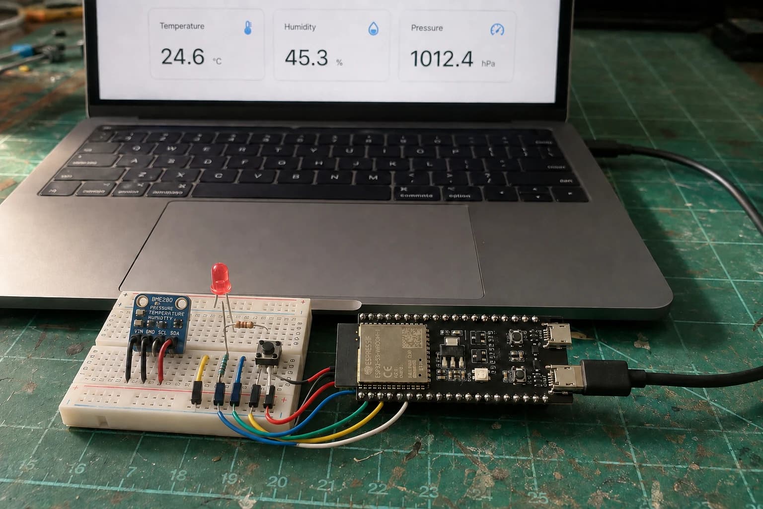
The first six parts covered choosing a board, uploading code, GPIO, sensors, Wi-Fi, and BLE. In this final part, we stop testing isolated pieces and build a device with explicit requirements, failure states, and completion criteria: the Room Comfort Monitor.
It reads a BME280 every two seconds, lights an LED when the room becomes too hot or humid, lets you mute the warning with a button, and displays the complete state on a local dashboard.
BME280 + button → ESP32 → LED + Wi-Fi dashboard
BLE from P6 is not forgotten. In a real product, it can handle first-time Wi-Fi provisioning or nearby access without a router. The first sketch uses only Wi-Fi because a complete project does not need every feature enabled at once.
Begin with requirements, not code
The project is complete when:
- Temperature, humidity, and pressure update every two seconds.
- The LED turns on at
30 °Cor70%humidity and above. - The button enables or disables the warning without multiple changes from contact bounce.
- The dashboard shows readings, room state, and alarm state.
- A JSON endpoint is available for future integration.
- Losing Wi-Fi does not stop sensor sampling or the button.
- Firmware retries Wi-Fi without becoming trapped in an endless wait loop.
The boundary matters too: this is a room-comfort observer, not a safety device. It does not replace a smoke, toxic-gas, or medical alarm.
Parts and pin mapping
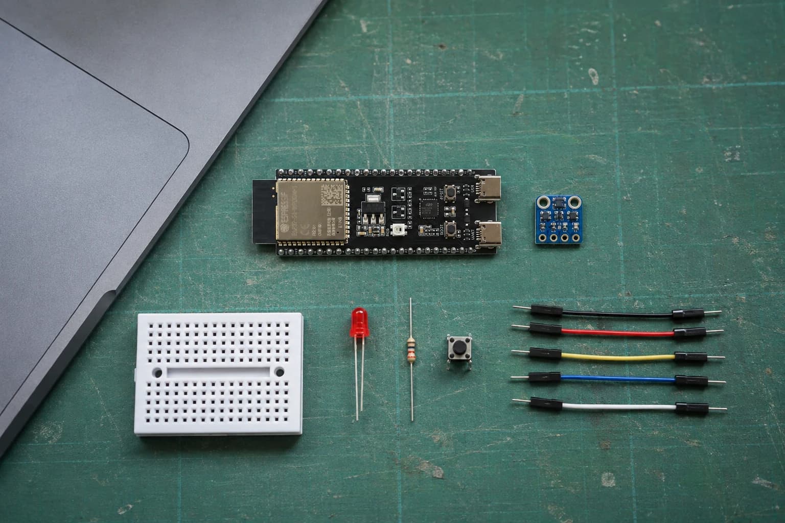
Confirming the parts and pin map before wiring avoids debugging hardware and firmware at the same time.
| Part | ESP32-S3-DevKitC-1 | Note |
|---|---|---|
| BME280 VCC | 3V3 | Do not assume 5 V is safe before checking the breakout |
| BME280 GND | GND | All modules share ground |
| BME280 SDA | GPIO4 | I2C data |
| BME280 SCL | GPIO5 | I2C clock |
| LED anode | GPIO2 through 220 Ω | Cathode to GND |
| Pushbutton | GPIO6 and GND | Uses INPUT_PULLUP; pressed is LOW |
GPIO2 and GPIO6 are both exposed on the ESP32-S3-DevKitC-1 v1.1 headers. If you use another board, check that board's pinout and change the constants. Do not wire by copying physical positions from a photo.
You also need the same secrets.h used in P5:
#pragma once

constexpr char WIFI_SSID[] = "YOUR_2_4_GHZ_SSID";
constexpr char WIFI_PASSWORD[] = "YOUR_WIFI_PASSWORD";
Keep the real file out of Git and commit only a secrets.example.h containing placeholders.
Give each firmware block one responsibility
A readable loop() should only coordinate:
handle HTTP → read button → sample sensor → update LED → recover Wi-Fi
Each block gets its own millis() timer. Nothing holds the CPU in an endless while. HTTP handlers change state or return data; they do not perform I2C reads or wait for the network.
Complete sketch
The code below keeps HTML in flash, avoids assembling many temporary String objects per request, and uses JSON as the boundary between firmware and dashboard.
#include <Arduino.h>
#include <WiFi.h>
#include <WebServer.h>
#include <Wire.h>
#include <Adafruit_BME280.h>
#include "secrets.h"

constexpr uint8_t SDA_PIN = 4;
constexpr uint8_t SCL_PIN = 5;
constexpr uint8_t LED_PIN = 2;
constexpr uint8_t BUTTON_PIN = 6;
constexpr uint8_t BME280_ADDRESS = 0x77;

constexpr float TEMP_WARNING_C = 30.0F;
constexpr float HUMIDITY_WARNING_PERCENT = 70.0F;
constexpr uint32_t SAMPLE_INTERVAL_MS = 2000;
constexpr uint32_t WIFI_RETRY_INTERVAL_MS = 10000;
constexpr uint32_t BUTTON_DEBOUNCE_MS = 40;

WebServer server(80);
Adafruit_BME280 bme;

bool sensorReady = false;
bool readingValid = false;
bool alarmEnabled = true;
bool warningActive = false;
bool wasWiFiConnected = false;

float temperature = NAN;
float humidity = NAN;
float pressure = NAN;

int lastButtonReading = HIGH;
int stableButtonState = HIGH;
uint32_t buttonChangedAt = 0;
uint32_t lastSampleAt = 0;
uint32_t lastWiFiAttemptAt = 0;

const char PAGE[] PROGMEM = R"HTML(
<!doctype html>
<html lang="en">
<meta name="viewport" content="width=device-width,initial-scale=1">
<title>Room Comfort Monitor</title>
<style>
  body{font:16px system-ui;margin:0;background:#eef2f5;color:#17202a}
  main{max-width:760px;margin:40px auto;padding:0 18px}
  .grid{display:grid;grid-template-columns:repeat(3,1fr);gap:12px}
  .card{background:#fff;padding:18px;border-radius:14px;box-shadow:0 4px 18px #0001}
  strong{display:block;font-size:1.6rem;margin-top:8px}
  #state{padding:14px;border-radius:12px;background:#dff5e6;margin:16px 0}
  button{border:0;border-radius:10px;padding:12px 16px;background:#17202a;color:#fff}
  @media(max-width:620px){.grid{grid-template-columns:1fr}}
</style>
<main>

  <h1>Room Comfort Monitor</h1>

  <div id="state">Loading...</div>
  <div class="grid">
    <div class="card">Temperature<strong id="t">--</strong></div>
    <div class="card">Humidity<strong id="h">--</strong></div>
    <div class="card">Pressure<strong id="p">--</strong></div>
  </div>
  <p>Alarm: <b id="alarm">--</b></p>
  <button onclick="toggleAlarm()">Toggle alarm</button>
</main>
<script>
async function refresh(){
  try{
    const r=await fetch('/api/status',{cache:'no-store'});
    const d=await r.json();
    document.getElementById('t').textContent=d.valid?d.temperature.toFixed(1)+' °C':'--';
    document.getElementById('h').textContent=d.valid?d.humidity.toFixed(1)+' %':'--';
    document.getElementById('p').textContent=d.valid?d.pressure.toFixed(1)+' hPa':'--';
    document.getElementById('alarm').textContent=d.alarmEnabled?'enabled':'muted';
    const state=document.getElementById('state');
    state.textContent=d.status;
    state.style.background=d.warning?'#ffd9d5':'#dff5e6';
  }catch(e){ document.getElementById('state').textContent='ESP32 offline'; }
}
async function toggleAlarm(){
  await fetch('/api/alarm/toggle',{method:'POST'});
  refresh();
}
refresh(); setInterval(refresh,2000);
</script>
</html>
)HTML";

void updateOutput() {
  warningActive = readingValid &&
      (temperature >= TEMP_WARNING_C ||
       humidity >= HUMIDITY_WARNING_PERCENT);
  digitalWrite(LED_PIN, alarmEnabled && warningActive ? HIGH : LOW);
}

void sampleSensor() {
  if (!sensorReady) {
    readingValid = false;
    updateOutput();
    return;
  }

  const float nextTemperature = bme.readTemperature();
  const float nextHumidity = bme.readHumidity();
  const float nextPressure = bme.readPressure() / 100.0F;

  readingValid = !isnan(nextTemperature) &&
                 !isnan(nextHumidity) &&
                 !isnan(nextPressure);
  if (readingValid) {
    temperature = nextTemperature;
    humidity = nextHumidity;
    pressure = nextPressure;
  }
  updateOutput();
}

void updateButton(uint32_t now) {
  const int reading = digitalRead(BUTTON_PIN);
  if (reading != lastButtonReading) {
    lastButtonReading = reading;
    buttonChangedAt = now;
  }

  if (now - buttonChangedAt >= BUTTON_DEBOUNCE_MS &&
      reading != stableButtonState) {
    stableButtonState = reading;
    if (stableButtonState == LOW) {
      alarmEnabled = !alarmEnabled;
      updateOutput();
      Serial.printf("Alarm %s\n", alarmEnabled ? "enabled" : "muted");
    }
  }
}

void sendStatus() {
  char readings[128];
  if (readingValid) {
    snprintf(readings, sizeof(readings),
             "\"temperature\":%.2f,\"humidity\":%.2f,\"pressure\":%.2f",
             temperature, humidity, pressure);
  } else {
    snprintf(readings, sizeof(readings),
             "\"temperature\":null,\"humidity\":null,\"pressure\":null");
  }

  const char *status = !readingValid ? "Sensor unavailable" :
                       warningActive ? "Check room conditions" :
                                       "Room looks comfortable";
  char json[320];
  snprintf(json, sizeof(json),
           "{%s,\"valid\":%s,\"warning\":%s,"
           "\"alarmEnabled\":%s,\"status\":\"%s\"}",
           readings,
           readingValid ? "true" : "false",
           warningActive ? "true" : "false",
           alarmEnabled ? "true" : "false",
           status);
  server.sendHeader("Cache-Control", "no-store");
  server.send(200, "application/json", json);
}

void configureServer() {
  server.on("/", HTTP_GET, []() {
    server.send_P(200, "text/html", PAGE);
  });
  server.on("/api/status", HTTP_GET, sendStatus);
  server.on("/api/alarm/toggle", HTTP_POST, []() {
    alarmEnabled = !alarmEnabled;
    updateOutput();
    sendStatus();
  });
  server.onNotFound([]() {
    server.send(404, "text/plain", "Not found");
  });
  server.begin();
}

void startWiFi() {
  WiFi.mode(WIFI_STA);
  WiFi.setAutoReconnect(true);
  WiFi.begin(WIFI_SSID, WIFI_PASSWORD);
  lastWiFiAttemptAt = millis();
}

void updateWiFi(uint32_t now) {
  const bool connected = WiFi.status() == WL_CONNECTED;
  if (!connected &&
      now - lastWiFiAttemptAt >= WIFI_RETRY_INTERVAL_MS) {
    lastWiFiAttemptAt = now;
    WiFi.reconnect();
  }

  if (connected && !wasWiFiConnected) {
    Serial.print("Dashboard: http://");
    Serial.println(WiFi.localIP());
  } else if (!connected && wasWiFiConnected) {
    Serial.println("Wi-Fi lost; local monitoring continues.");
  }
  wasWiFiConnected = connected;
}

void setup() {
  Serial.begin(115200);
  pinMode(LED_PIN, OUTPUT);
  pinMode(BUTTON_PIN, INPUT_PULLUP);
  digitalWrite(LED_PIN, LOW);

  lastButtonReading = digitalRead(BUTTON_PIN);
  stableButtonState = lastButtonReading;

  Wire.begin(SDA_PIN, SCL_PIN);
  sensorReady = bme.begin(BME280_ADDRESS, &Wire);
  sampleSensor();

  configureServer();
  startWiFi();
  Serial.println(sensorReady ? "BME280 ready." : "BME280 unavailable.");
}

void loop() {
  server.handleClient();

  const uint32_t now = millis();
  updateButton(now);

  if (now - lastSampleAt >= SAMPLE_INTERVAL_MS) {
    lastSampleAt = now;
    sampleSensor();
  }

  updateWiFi(now);
  delay(2);
}
If your scanner finds the BME280 at 0x76, change only BME280_ADDRESS. If an active-low LED module works backwards, swap HIGH and LOW in updateOutput().
Bring up one layer at a time
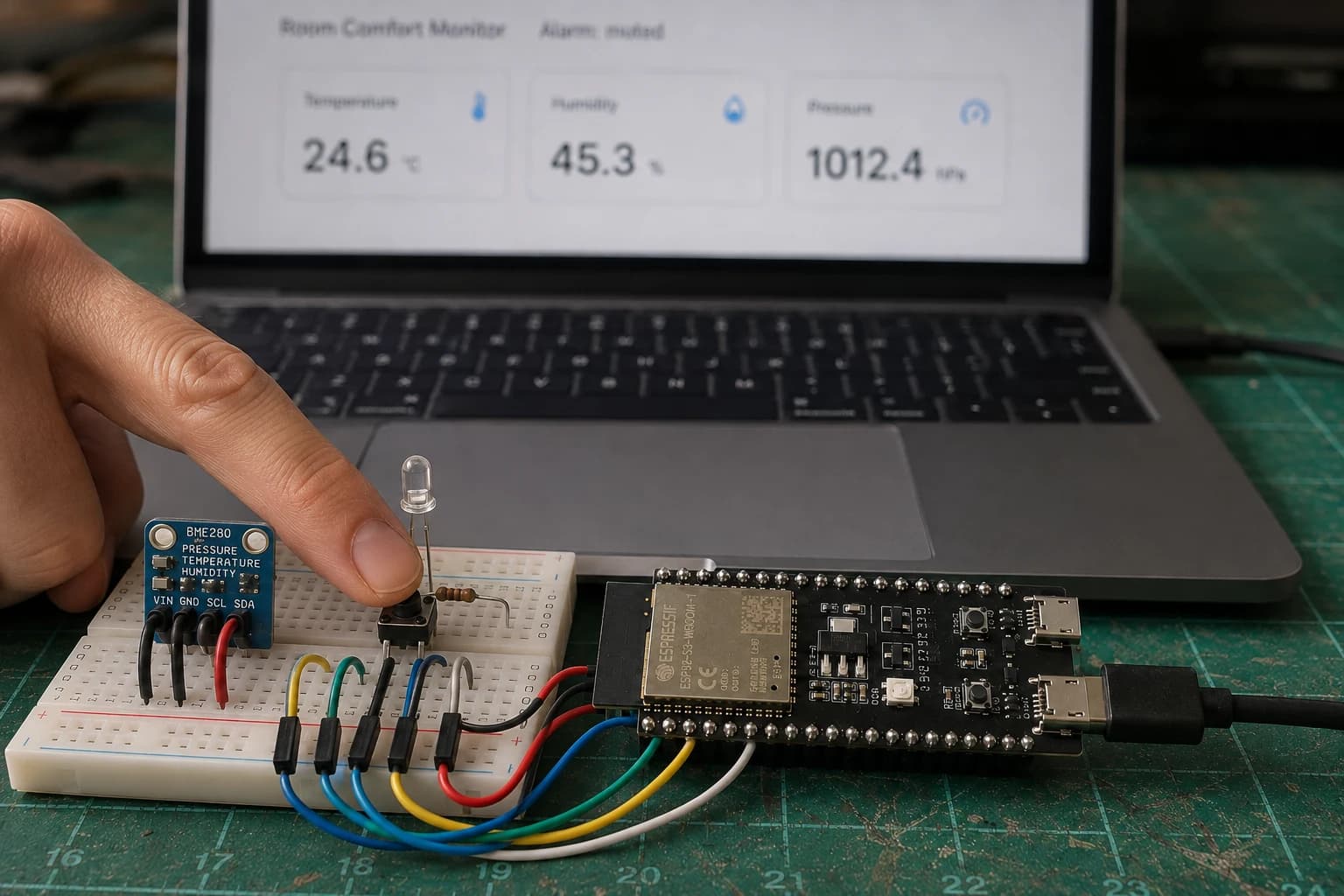
The button enables or disables the local warning while sensor sampling and the dashboard continue running.
I test in this order:
- Power: the board boots reliably without random resets.
- I2C: a scanner finds
0x76or0x77. - Sensor: Serial shows three plausible readings.
- Output: a separate Blink sketch turns the external LED on and off.
- Input: Serial logs only one change per button press.
- Network: ESP32 gets an IP address and serves the dashboard.
- Integration: button and web both change
alarmEnabled; losing Wi-Fi does not freeze the LED in the wrong state.
This sounds slower, but it is usually faster than debugging a 200-line sketch before knowing whether SDA is plugged into the correct pin.
Test it as a device, not merely a web page
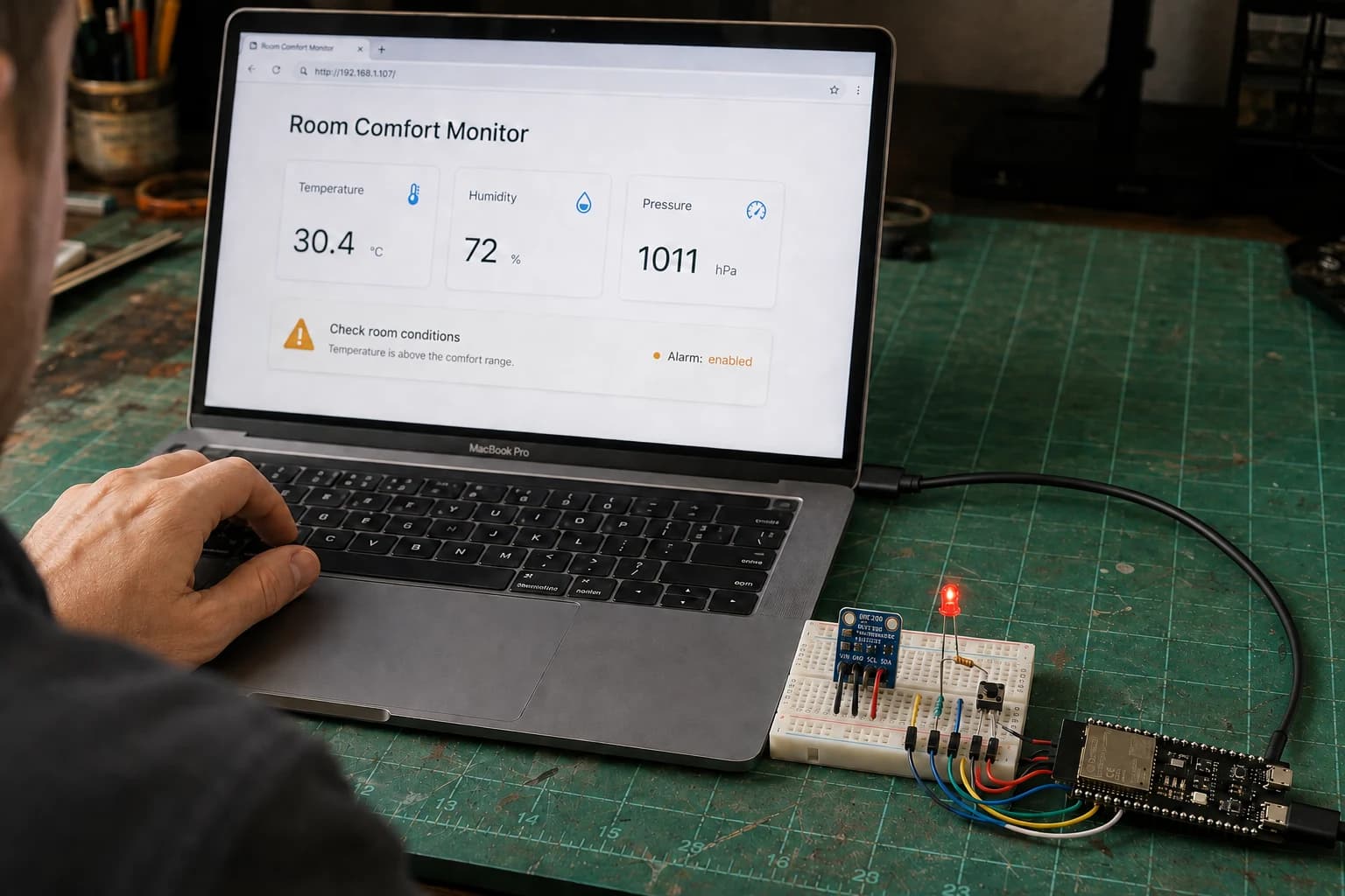
The final test covers sensor data, warning state, local control, and Wi-Fi recovery together.
| Test | Action | Expected result |
|---|---|---|
| Normal startup | Power on while the router is available | Readings, IP address, and dashboard appear |
| Missing BME280 | Remove power, disconnect sensor, then power on | Dashboard reports sensor unavailable; LED stays off |
| Wi-Fi loss | Temporarily turn off the router | Sensor and button continue; reconnect follows network recovery |
| Temperature warning | Warm the sensor gently with a hand, never a flame | Status changes above threshold; LED lights if alarm is enabled |
| Button bounce | Press the button once normally | State changes exactly once |
| Web control | Tap Toggle alarm | LED and JSON reflect the new state |
| Unknown client route | Open a nonexistent URL | HTTP 404 is returned without resetting firmware |
Do not place a hair dryer or other high-temperature source close to the BME280. The test only needs a trend; warmth from your hand is enough for a basic check.
When does the prototype become a small product?
A breadboard completes the lesson, not the product. Before long-term use, I would add:
- Soldered connections and an enclosure with airflow around the BME280.
- Physical distance between the sensor, regulator, ESP32, and hot exhaust air.
- Less LED activity for a battery-powered version.
- A setup page or BLE provisioning instead of hard-coded Wi-Fi credentials.
- Protection for control endpoints; this web server belongs only on a trusted LAN.
- Persistent settings with
Preferences, a watchdog, reset-reason logs, and OTA with recovery. - A soak test lasting hours or days, including deliberate router and power interruptions.
When you want a messier real-world step, the ESP32 Smart Garden adds multiple sensors, imperfect analog data, and an actuator that needs fail-safe behavior.
ESP32 Beginner Guide final checklist
- You can choose a specific development board instead of buying from a generic “ESP32” title.
- You can upload code, read Serial, and handle basic port or boot failures.
- You read the pinout before assigning GPIO.
- You bring up a sensor separately before integration.
- You understand when Wi-Fi, a web server, or BLE fits the problem.
- You separate input, sampling, output, network, and API responsibilities.
- You have tests for sensor failure, network loss, and rebooting.
- You do not commit credentials or expose a demo web server to the Internet.
This is the final part of the ESP32 Beginner Guide. If the Room Comfort Monitor keeps working through repeated network and power interruptions, you have crossed the hardest beginner boundary: you are no longer making code merely run; you are designing how a device behaves when conditions are imperfect.
References
Share
Keep exploring
Read next
Related articles
ESP32 Beginner Guide – P5: Wi-Fi and Web Server
Connect ESP32 to Wi-Fi, find its IP address, and build a local web server that displays BME280 temperature, humidity, and pressure in a browser.
ESP32 Beginner Guide – P4: Connecting Sensors
Connect digital, analog, and I2C sensors to ESP32; read temperature, humidity, and pressure from a BME280 and diagnose devices that are not detected.
ESP32 Beginner Guide – P6: Bluetooth Low Energy
Learn ESP32 BLE, GATT services, and characteristics by sending BME280 readings to a phone with Read and Notify.