

ESP32 Beginner Guide – P4: Connecting Sensors
Connect digital, analog, and I2C sensors to ESP32; read temperature, humidity, and pressure from a BME280 and diagnose devices that are not detected.
Share
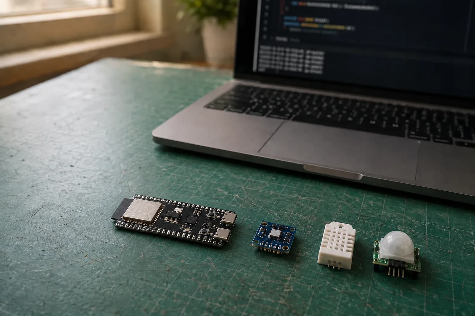
In P3: Pinout and GPIO, we selected safer pins, wired an LED, and avoided feeding 5 V signals into an ESP32. P4 turns that foundation into something useful: reading temperature, humidity, and pressure from a BME280 over I2C.
The goal is not to copy a wiring photo and hope. By the end, you will be able to identify a sensor interface, check its voltage, find its I2C address, and debug each layer separately.
A sensor and a sensor module are not quite the same
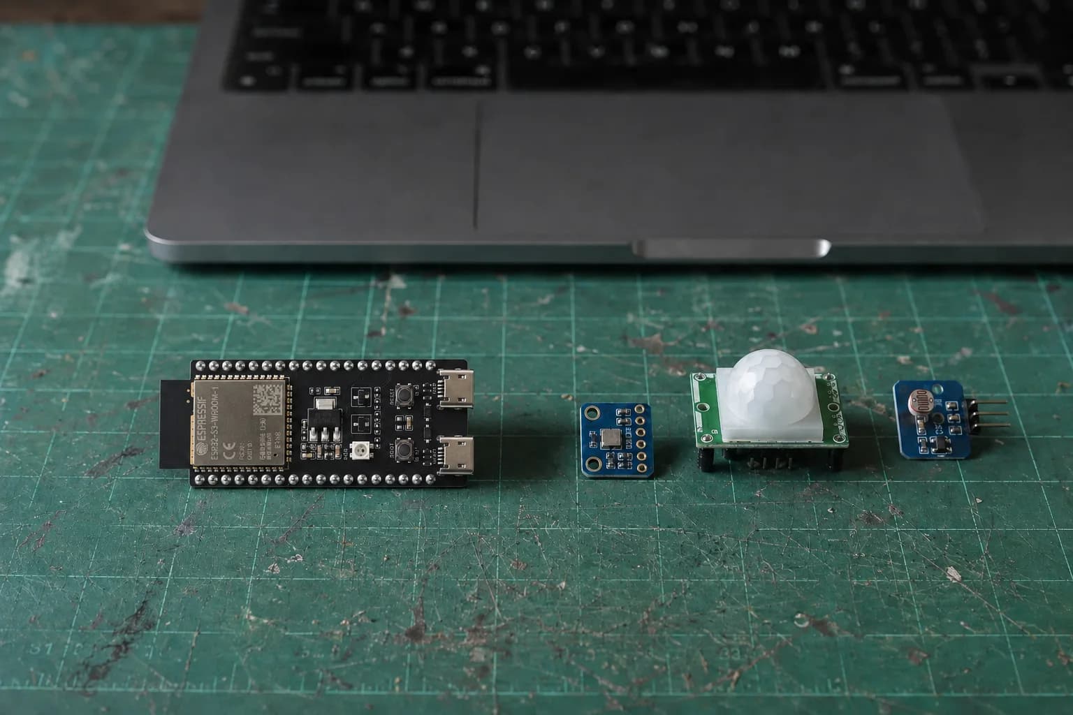
Before wiring, identify whether the sensor uses a digital signal, analog output, or a bus such as I2C.
The BME280 is a tiny Bosch sensor IC. What we usually buy is a breakout board: a PCB carrying the BME280, capacitors, pull-up resistors, and sometimes a regulator or level shifter. Two products labeled “BME280” can therefore have different pin counts and supply requirements.
Before connecting one, find the datasheet or schematic for the exact breakout in your hand. Do not assume that VIN means the same thing as 3V3, or that a module accepting 5 V power also returns GPIO-safe signals.
The three signal types you will see most often
| Type | Common labels | How ESP32 reads it | What to verify |
|---|---|---|---|
| Single digital signal | OUT, DO, DATA | digitalRead() or a timing-specific library | Whether HIGH is 3.3 V or 5 V; whether it needs a pull-up |
| Analog | AO, AOUT | analogRead() or analogReadMilliVolts() | The pin has ADC support; voltage stays within GPIO limits |
| Digital bus | SDA/SCL, MOSI/MISO/SCK/CS, TX/RX | I2C, SPI, or UART | Logic voltage, bus pins, address, or baud rate |
A DATA label does not guarantee that digitalRead() is enough. A DHT22, for example, transfers data with its own timing, while a module with a comparator may only return HIGH or LOW at a threshold. The part number and datasheet determine the code.
For analog sensors, analogRead() returns a raw value, while analogReadMilliVolts() uses calibration to return millivolts. Measurement range and attenuation differ across ESP32 families, so do not convert 0–4095 with a formula copied from another board.
Why I chose I2C and the BME280
I2C uses two signal lines:
SDAcarries data.SCLcarries the clock generated by the ESP32 when it acts as controller.
Several devices can share those two lines when their 7-bit addresses do not collide. SDA and SCL are open-drain lines and require pull-up resistors. Most BME280 breakouts include them, but you still need to know which voltage pulls them high. A breakout pulling SDA/SCL to 5 V must not connect directly to an ESP32.
The BME280 is a friendly first sensor because one module provides three measurements, has a mature open-source library, and needs only the I2C bus. The IC can use address 0x76 or 0x77, depending on the SDO state and breakout design.
Check the exact module before applying power
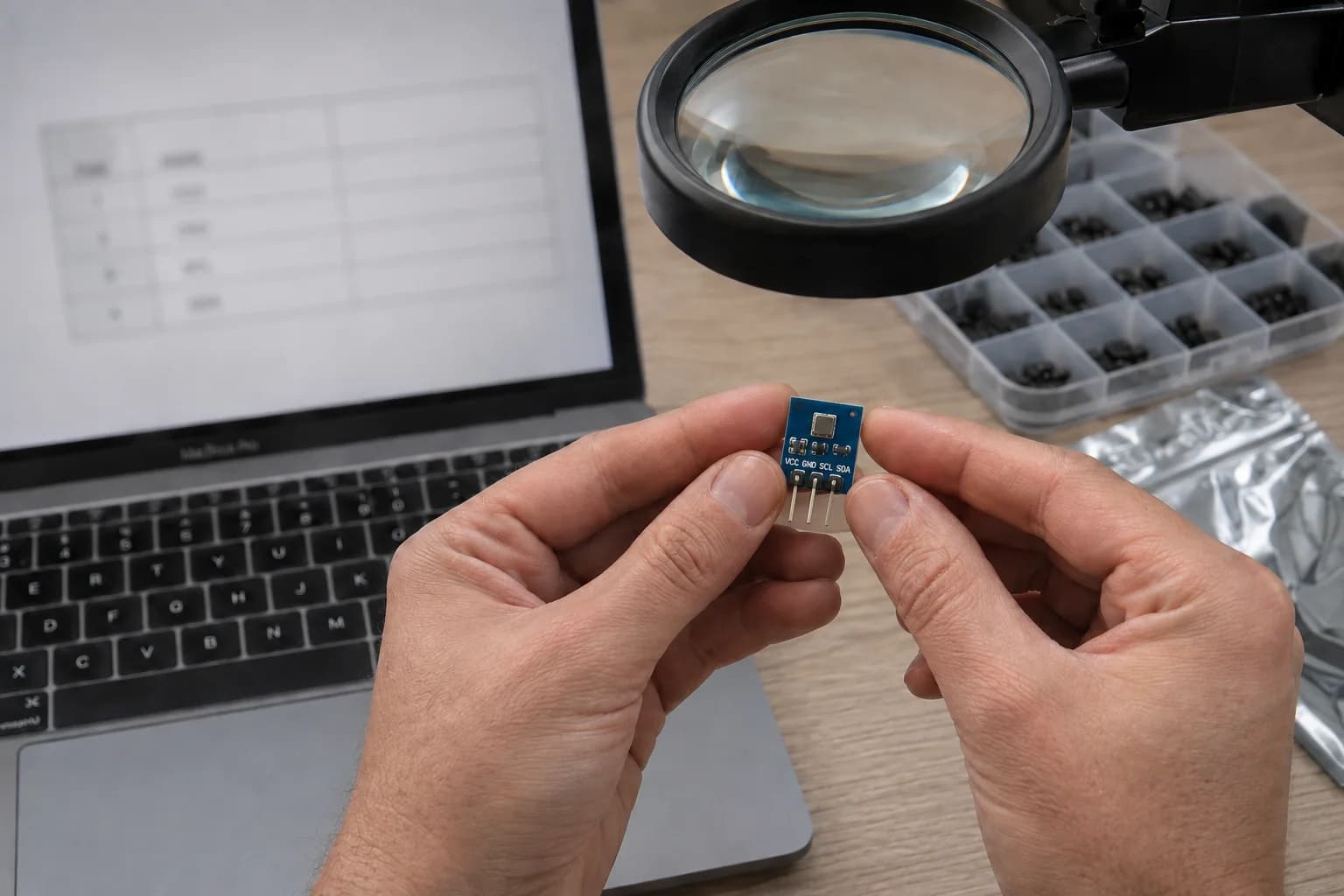
Breakouts carrying the same BME280 name can use different regulators, pull-ups, and pin labels.
Some listings show a BME280 photo but ship a BMP280, and boards can print pins in a different order. Before wiring, I check:
- The PCB marking and chip code, if visible.
- The order of
VCC/VIN,GND,SDA/SDI, andSCL/SCK. - Whether the breakout contains regulation and level shifting or is 3.3 V only.
- Supply and logic voltages in that breakout's own documentation.
This exercise assumes a four-pin I2C BME280 module that works correctly at 3.3 V. If yours exposes seven pins named VIN, 3Vo, GND, SCK, SDI, CS, and SDO, follow its manufacturer pinout instead of forcing it into the table below.
Wire the BME280 to ESP32
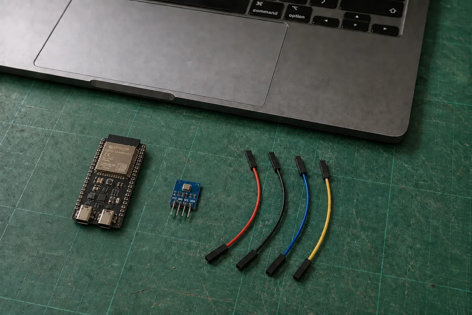
Unplug USB before connecting 3V3, GND, SDA, and SCL; wire colors aid tracking but never replace pin labels.
Unplug USB before wiring. For the ESP32-S3-DevKitC-1 or ESP32-C3-DevKitM-1 used in this series:
| BME280 | ESP32-S3 / ESP32-C3 | Role |
|---|---|---|
VCC or VIN | 3V3 | 3.3 V supply |
GND | GND | Common ground |
SDA | GPIO4 | I2C data |
SCL | GPIO5 | I2C clock |
On a classic ESP32-DevKitC with a WROOM module, you can use GPIO21 for SDA and GPIO22 for SCL. These are explicit choices for the named boards, not a universal ESP32 pinout. Check whether GPIO4/5 is already occupied when your board includes a display, camera, or onboard sensor.
Scan the bus before installing a sensor library
An I2C scanner separates wiring faults from library faults. Upload this sketch and open Serial Monitor at 115200 baud:
#include <Wire.h>

constexpr uint8_t SDA_PIN = 4;
constexpr uint8_t SCL_PIN = 5;

void setup() {
  Serial.begin(115200);
  delay(500);

  if (!Wire.begin(SDA_PIN, SCL_PIN)) {
    Serial.println("I2C init failed");
    return;
  }

  Serial.println("Scanning I2C bus...");
  uint8_t found = 0;

  for (uint8_t address = 1; address < 127; ++address) {
    Wire.beginTransmission(address);
    if (Wire.endTransmission() == 0) {
      Serial.printf("Found device at 0x%02X\n", address);
      ++found;
    }
  }

  Serial.printf("Scan complete: %u device(s)\n", found);
}

void loop() {}
The expected result is 0x76 or 0x77. If no device appears, do not switch libraries yet. Remove power, then check VCC, common GND, swapped SDA/SCL, pin constants, and breadboard contact.
Read temperature, humidity, and pressure
Open Library Manager in Arduino IDE and install:
Adafruit BME280 LibraryAdafruit Unified Sensor
Then use the address reported by the scanner:
#include <Wire.h>
#include <Adafruit_BME280.h>

constexpr uint8_t SDA_PIN = 4;
constexpr uint8_t SCL_PIN = 5;
constexpr uint8_t BME280_ADDRESS = 0x76; // use 0x77 if that is what the scanner found

Adafruit_BME280 bme;

void setup() {
  Serial.begin(115200);
  delay(500);

  if (!Wire.begin(SDA_PIN, SCL_PIN)) {
    Serial.println("Cannot start I2C");
    while (true) delay(1000);
  }

  if (!bme.begin(BME280_ADDRESS, &Wire)) {
    Serial.println("BME280 not found. Check address and wiring.");
    while (true) delay(1000);
  }
}

void loop() {
  Serial.printf("Temperature: %.2f C\n", bme.readTemperature());
  Serial.printf("Humidity: %.2f %%\n", bme.readHumidity());
  Serial.printf("Pressure: %.2f hPa\n\n", bme.readPressure() / 100.0F);
  delay(2000);
}
The library returns BME280 pressure in Pa, so the sketch divides by 100.0F for hPa. A breakout may also read slightly warm from nearby regulators, the ESP32, or the MacBook Pro; a module placed next to the board is not automatically a calibrated room thermometer.
When the sensor does not work
| Symptom | Check first |
|---|---|
| Scanner reports zero devices | 3.3 V supply, common GND, swapped SDA/SCL, wrong GPIO, or broken wire |
Scanner finds 0x77, code uses 0x76 | Set BME280_ADDRESS to the scanner result |
Address appears but bme.begin() fails | The module may be a BMP280, power may be unstable, or the library may be wrong |
| Readings work intermittently | Long wires, poor contact, unsuitable pull-ups, or excessive bus speed |
| Temperature reads unusually high | Self-heating, a nearby heat source, or insufficient settling time |
| Analog values become noisy with Wi-Fi | Sample repeatedly; check supply, ground, ADC choice, and limits for the exact ESP32 family |
Debug in the order power → ground → pins → address → library → data. Changing three things at once usually hides the cause.
Checklist before P5
- You know whether the sensor uses digital, analog, I2C, SPI, or UART.
- You checked supply and logic voltage for the exact breakout.
- The ESP32 and sensor share ground.
- SDA/SCL constants match the wires instead of blindly relying on defaults.
- The I2C scanner finds an address before the sensor library runs.
- The sketch handles sensor initialization failure.
In P5: Wi-Fi and Web Server, we will put sensor data on the local network with a bounded connection attempt and no endless reconnect loop inside loop().
References
Share
Keep exploring
Read next
Related articles
ESP32 Beginner Guide – P7: Build a Complete ESP32 Project
Finish the series with a Room Comfort Monitor: ESP32 reads a BME280, controls a warning LED and serves a local Wi-Fi dashboard.
ESP32 Beginner Guide – P5: Wi-Fi and Web Server
Connect ESP32 to Wi-Fi, find its IP address, and build a local web server that displays BME280 temperature, humidity, and pressure in a browser.
ESP32 Beginner Guide – P6: Bluetooth Low Energy
Learn ESP32 BLE, GATT services, and characteristics by sending BME280 readings to a phone with Read and Notify.