

How to Hand-Solder SMD Components for Beginners
A beginner-friendly SMD soldering guide covering tools, easy parts, resistors, capacitors, multi-pin ICs, flux, hot air, and PCB inspection.
Share
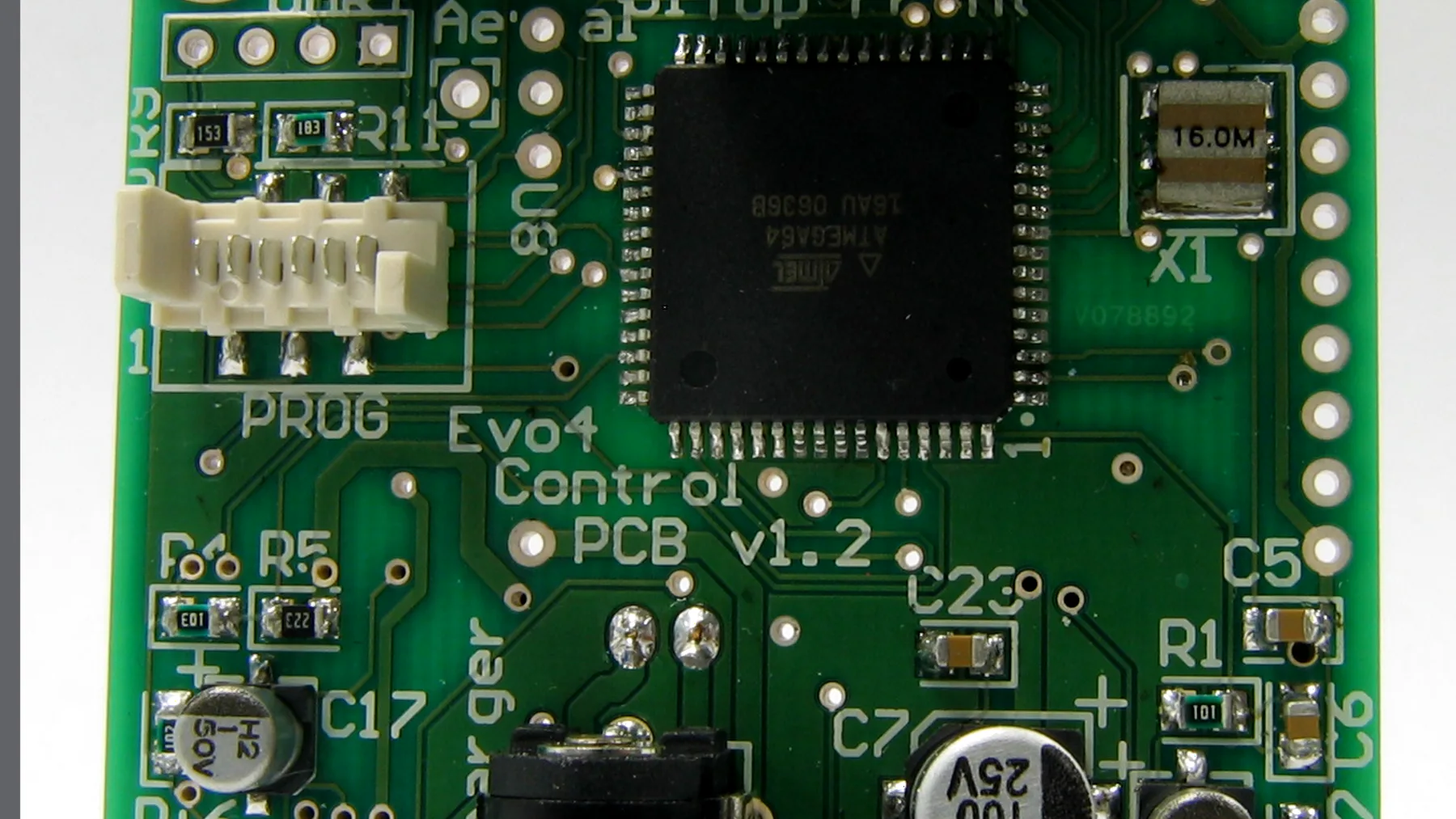
The first time you look at a PCB full of SMD parts, it is completely normal to feel a little overwhelmed. The components are small, the pads are close together, and one small nudge can leave a part crooked or bridge two IC pins.
But SMD soldering is not as scary as it looks. For common packages such as 0603/0805 resistors and capacitors, SOT-23 parts, SOIC chips, and small modules, you can absolutely solder them by hand with a normal soldering iron. The trick is to use the right basic tools, add enough flux, and work through the board calmly.
This is the workflow I usually follow when assembling PCBs by hand. It is not a production SMT process. It is just a practical way to get started with DIY boards, prototypes, and small lab builds without feeling defeated by tiny parts.
Tools Worth Preparing
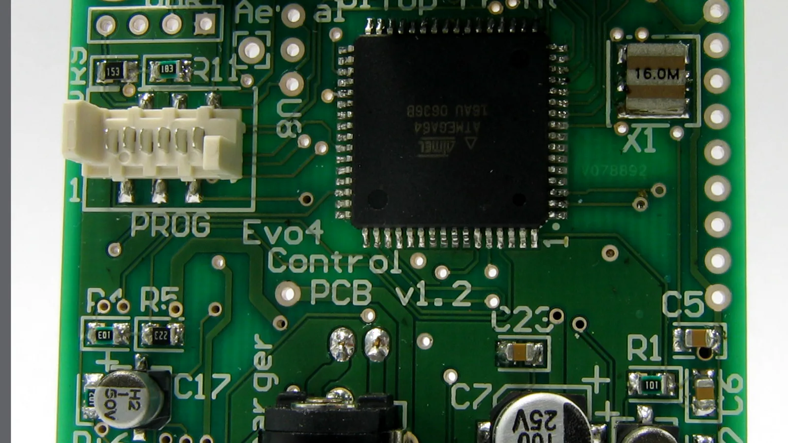
You do not need to buy a full rework bench at the beginning. A small, practical setup is enough for a lot of boards:
- A temperature-controlled soldering iron.
- A small tip, either a small chisel tip or a reasonably fine conical tip.
- Thin solder wire, around 0.3-0.6 mm.
- Flux.
- Fine tweezers.
- Desoldering braid.
- IPA and a small brush for cleaning the PCB.
- A magnifier or microscope if you often solder very small parts.
If you later work with many ICs, QFN packages, or parts with pads underneath, hot air, solder paste, and a stencil will help a lot. But for a beginner, I would put good flux near the top of the list. Good flux makes solder flow more smoothly, keeps joints cleaner, and makes mistakes much easier to fix.
Start With Easy Parts
Do not make your first practice board harder than it needs to be. Start with parts that are large enough to see clearly and easy to correct:
- 0805 resistors.
- 0805 capacitors.
- 0603 resistors or capacitors.
- SMD LEDs.
- SOIC ICs.
- SOT-23 parts.
I would not start with QFN, BGA, or very fine-pitch packages. At the beginning, you are mostly learning the feel of the tweezers, how solder behaves with flux, and when to stop heating a pad.
Soldering SMD Resistors and Capacitors
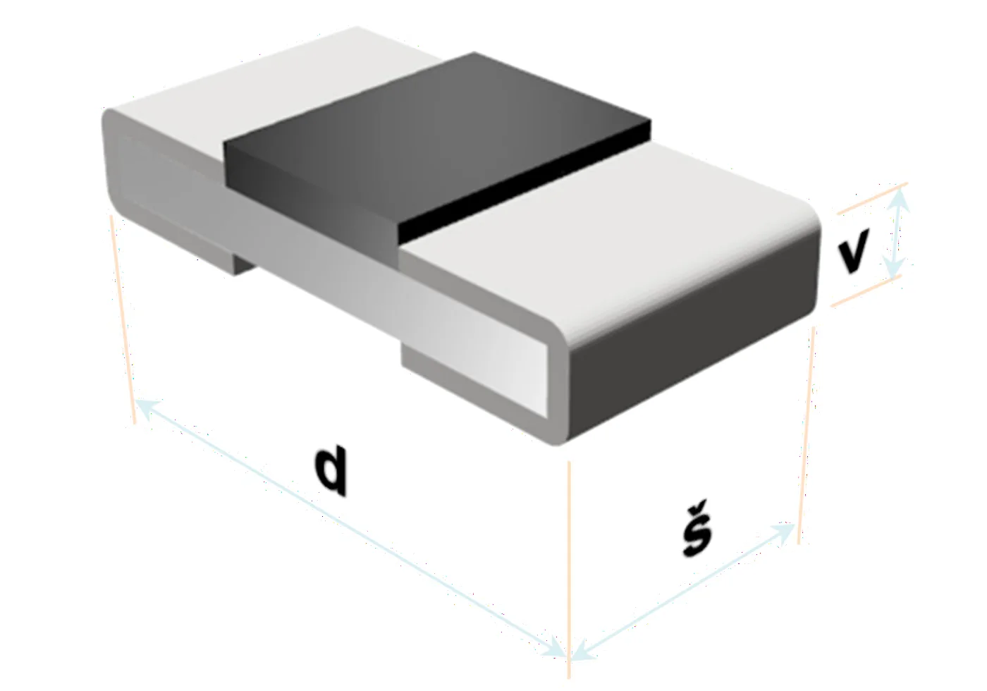
For two-terminal parts, the easiest method is to anchor one side first.
- Add a small amount of solder to one pad.
- Hold the component in place with tweezers.
- Reheat the pre-tinned pad and gently slide the component onto the footprint.
- Let the solder cool so one side holds the part.
- Solder the other side.
- Touch up the first joint if needed.
This is where beginners often add too much solder. A good joint does not need to be big. It only needs to wet the pad and the component terminal cleanly. If the solder looks dull, clumpy, or refuses to flow nicely, try adding flux before adding more solder.
Soldering Multi-Pin ICs
For SOIC, TSSOP, and other leaded ICs, I usually do this:
- Place the IC in the correct orientation and check the pin 1 mark.
- Tack one corner pin.
- Check whether the IC is aligned with the footprint.
- Tack one pin on the opposite corner to lock it in place.
- Apply flux across the full row of pins.
- Gently drag the iron along the pins.
This technique is often called drag soldering. You do not need every pin to look perfect on the first pass. If two pins bridge, add flux and drag the iron across them again. If there is still too much solder, use desoldering braid to remove the excess, then inspect the pins under good light.
Stay calm here. A lot of SMD joints that look like a disaster at first only need a little flux and a second pass.
Flux Matters More Than More Solder
One common beginner habit is adding more solder whenever a joint does not look right. That usually creates:
- Oversized joints.
- Bridged IC pins.
- More cleanup work.
In many cases, what you need is flux, not more solder. Flux helps solder flow evenly and wet the pad and component lead. When you are fixing bridged IC pins, flux also helps the iron pull solder away from the short.
Short version: when a joint starts getting hard to control, reach for flux first.
Soldering Iron Temperature
There is no single perfect temperature for every solder alloy, PCB, and iron tip. But for hand soldering, these are reasonable starting points:
- 320-350 degC for leaded solder.
- 350-380 degC for lead-free solder.
The exact number matters less than contact time. Do not hold the iron on a small pad for too long, because too much heat can lift pads, damage parts, or discolor the PCB.
For most small SMD joints, a few seconds is enough. If the joint is not improving, stop, add flux, let the area cool for a moment, and try again. Do not keep pushing heat into the board just because you want to finish the joint quickly.
A Good Assembly Order
When a PCB has many parts, I usually solder from low to tall and from small to large:
- Small passives such as resistors and capacitors.
- Low-profile ICs.
- Small connectors.
- Modules.
- Large connectors, buttons, tall capacitors, and mechanical parts.
The reason is simple: large parts get in the way. If you solder them too early, tweezers and the iron tip become harder to move around the small parts nearby. Starting with the low components also helps the board stay flat while you work.
When Hot Air Helps
A soldering iron is enough for many normal SMD parts. You do not need hot air on your first day.
Hot air becomes useful when you work with:
- QFN or DFN packages.
- ICs with an exposed pad underneath.
- High-pin-count connectors.
- Parts that are too small to solder pad by pad.
- IC removal or rework.
When using hot air, solder paste is usually easier than solder wire. Apply a controlled amount of paste to the pads, place the component, then heat the area evenly until the solder melts. If the part is placed reasonably well, surface tension will often pull it into a surprisingly nice position.
Beginner Mistakes to Watch For
Using too much solder
A solder joint does not need to be a large blob. Extra solder makes bridges more likely, especially on fine-pitch ICs.
Skipping flux
This is one of the main reasons SMD soldering feels harder than it really is. Good flux makes the whole process much more forgiving.
Pressing the iron too hard
You only need enough contact to transfer heat into the pad and component lead. Pressing harder does not make the joint better.
Heating the pad for too long
Small pads can lift if they are overheated. If things start to get messy, pause for a few seconds and let the area cool before continuing.
Forgetting component orientation
Pay special attention to ICs, LEDs, diodes, and polarized capacitors. Checking orientation before soldering is much faster than removing a reversed part after applying power.
Inspect Before Power
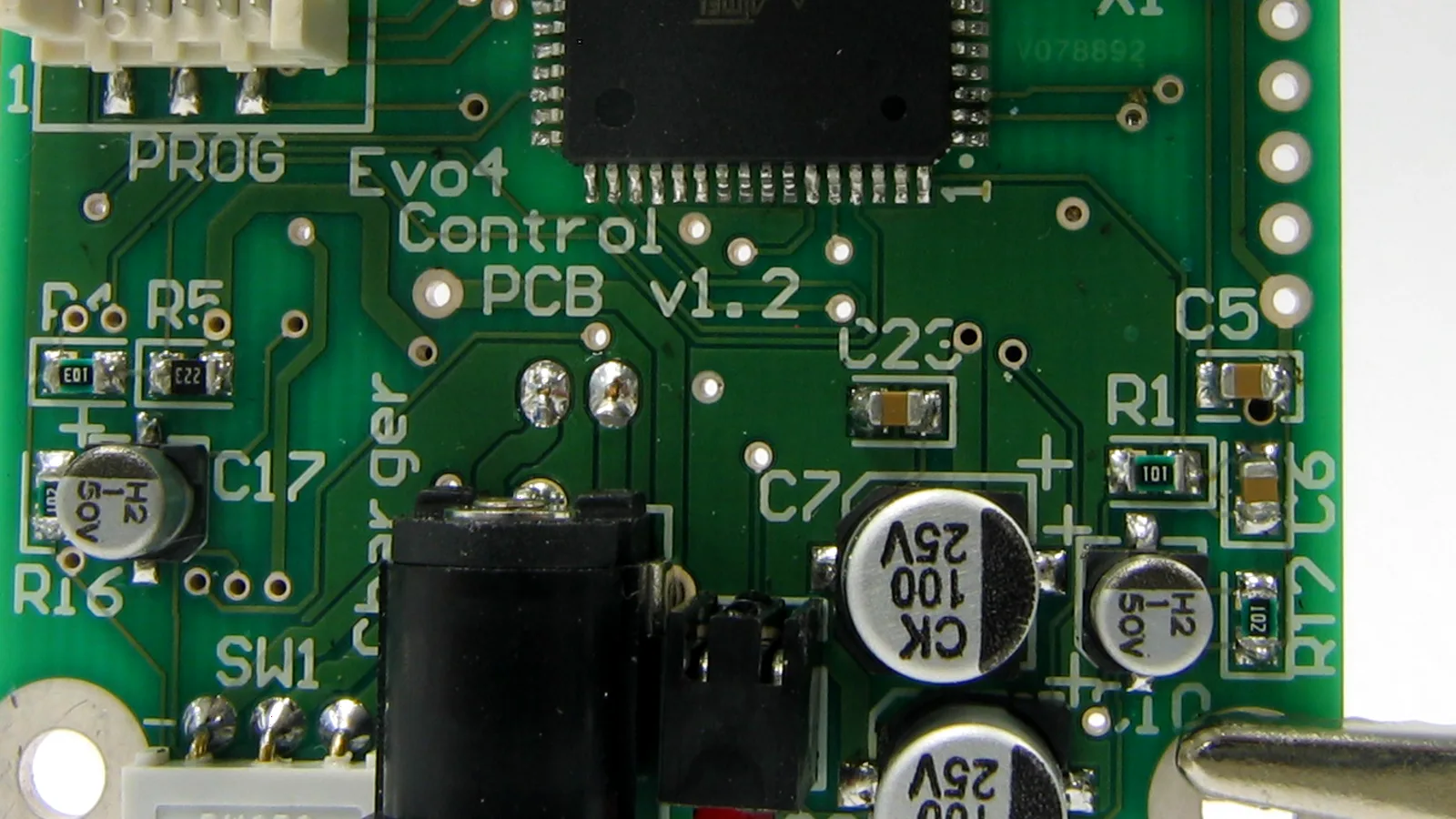
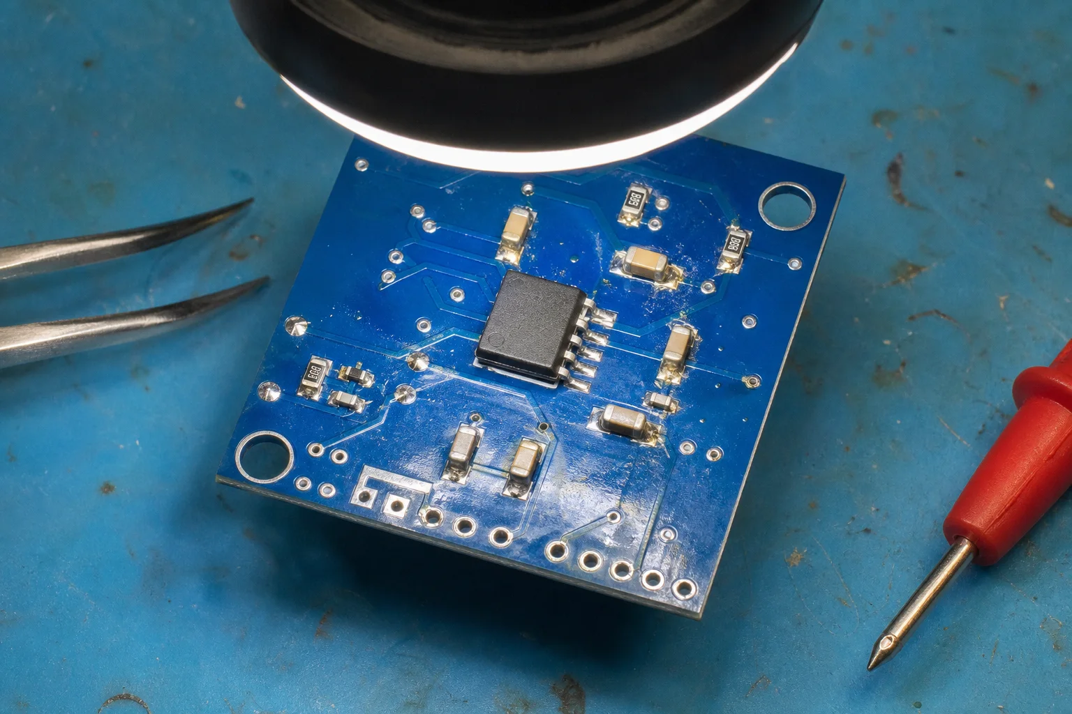
After soldering, do not power the board right away. Take a few minutes to inspect it:
- Are any IC pins bridged?
- Are any parts shifted off their pads?
- Are any polarized components installed backward?
- Are there solder balls or stray bridges on the PCB?
Then use a multimeter in continuity mode between power and GND. If it reports a short, inspect the board again before applying power. Finally, clean the flux residue with IPA so the PCB is easier to inspect, easier to debug, and nicer to look at.
Conclusion
SMD soldering is not as hard as it first appears. For common resistors, capacitors, and leaded ICs, a decent soldering iron, good tweezers, and flux are enough for most DIY PCB work.
If you are just starting, practice with 0805 parts and SOIC chips first. Once you understand how solder flows and how to control parts with tweezers, moving to 0603, TSSOP, or hot-air work on QFN packages becomes much easier.
The most important habits are simple: use less solder, use enough flux, avoid long heat contact, and always inspect the board before powering it.
References
These sources are useful background material for checking terminology, limits, and engineering recommendations before applying the notes to a real prototype.
- SparkFun Learn: soldering tutorials
- SparkFun Education: How to Solder
- SparkFun: Keep Calm and Solder On
Image credits and license
The cover is adapted from Wikimedia Commons "Soldering a 0805.jpg" by Aisart, licensed under CC BY-SA 3.0. The Nastrotek version was cropped, resized, and lightly color-adjusted and remains available under the same license. The PCB inspection image near the end of the article was created specifically for Nastrotek and is not copied from an existing board or product photograph.
Share
Keep exploring
Read next
Related articles
Net Classes and Trace Width: When Should a PCB Trace Be Wider?
A practical guide to PCB net classes and trace width for small boards: signal traces, 3V3, 5V, battery paths, ground, power vias, and a pre-Gerber checklist.
PCB Ground Planes: GND Is More Than a Net Name
A practical guide to PCB ground planes, return current, GND layout mistakes, stitching vias, decoupling paths, and copper pour checks.
Choosing Capacitors for Electronics: Simple Part, Easy Mistake
A beginner guide to choosing capacitors for circuits: capacitance, voltage rating, decoupling, ceramic types, DC bias, and ESP32 values.