

STM32 Beginner Guide P2: GPIO, Interrupts, and Timers from the First Example
Learn to configure GPIO, capture a button event with an EXTI interrupt, and create a periodic time base with a timer on STM32CubeIDE using a NUCLEO-G071RB board.
Share
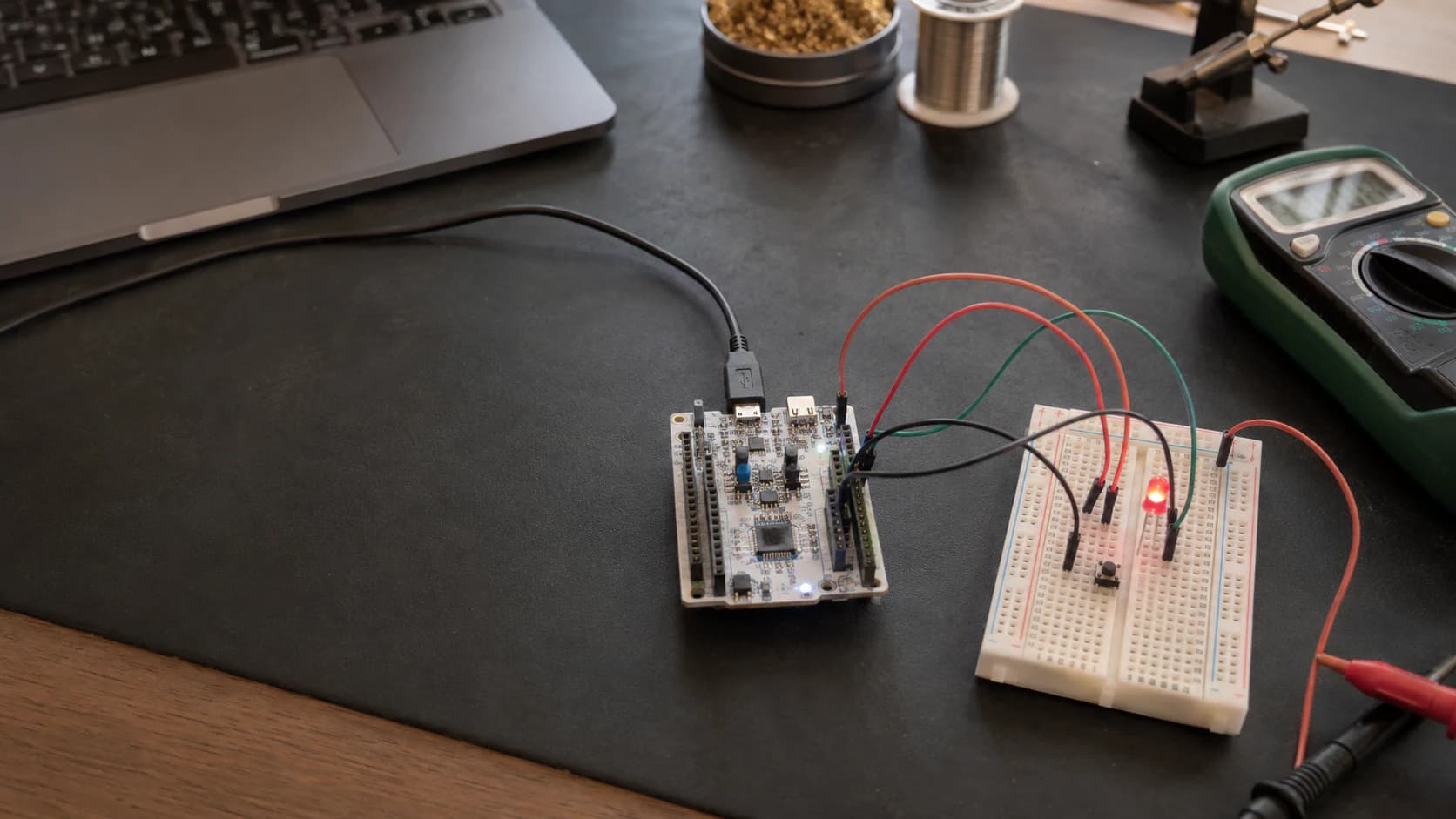
In P1: Getting Started with STM32, I chose the NUCLEO-G071RB as the reference board and separated STM32 chips, modules, and development boards. P2 is where we connect real hardware: one LED, one push button, and one timer.
Series: P1: Getting Started with STM32 · P2 is here · P3: UART, I2C, and SPI
The goal is not a large demo. I want you to see three basic ways firmware interacts with the outside world:
- GPIO reads or drives a logic level.
- An interrupt tells the CPU that an event has happened.
- A timer creates a regular time reference.
The examples use STM32CubeIDE, CubeMX, and HAL. ST also organizes GPIO/EXTI and timer examples in the STM32CubeG0 repository, so you can open the official source when you want to go deeper.
GPIO: a digital pin is more than HIGH and LOW
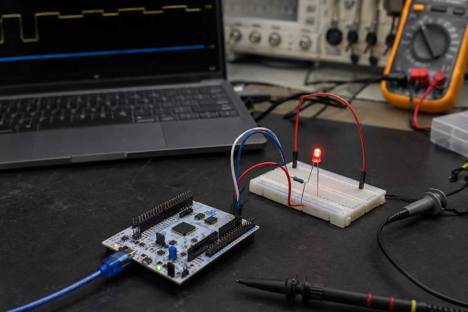
GPIO is only a control signal; the LED still needs a current-limiting resistor and a common ground.
GPIO is a general-purpose pin that can be configured as an input, output, or alternate function for another peripheral. At the basic level, you will use it in two ways:
- Output: STM32 drives an LED, relay driver, or enable signal.
- Input: STM32 reads a button, switch, or digital sensor signal.
NUCLEO-G071RB GPIO uses 3.3 V logic. HIGH is not a power supply for everything; it is a logic level. A GPIO should also not drive a motor, relay coil, or large load directly. Those loads need an appropriate transistor/MOSFET stage and separate power path.
Push-pull output
For a loose LED, the minimum circuit is:
GPIO ---- 330 Ω resistor ---- LED anode
GND  ------------------------ LED cathode
The resistor can be placed before or after the LED as long as it is in series and limits current. Do not connect an LED directly to a GPIO and remove the resistor just to see what happens.
In CubeMX, choose an unused GPIO, set it to GPIO_Output, use Push-Pull, select No pull, and start with low or medium speed. The generated symbol may be named LED_Pin and LED_GPIO_Port; the exact names depend on your project.
The smallest HAL example looks like this:
while (1)
{
    HAL_GPIO_TogglePin(LED_GPIO_Port, LED_Pin);
    HAL_Delay(500);
}
HAL_Delay(500) makes the LED change state every 500 ms. That is fine for the first demo, but it should not become the way you schedule the entire application. In the timer section, we will replace it with a non-blocking periodic event.
Input and floating state
An unconnected input can read HIGH or LOW unpredictably because of noise. That state is called floating. For a simple button, use an internal pull-up:
GPIO input ---- push button ---- GND
With a pull-up, a released button normally reads GPIO_PIN_SET, while a pressed button reads GPIO_PIN_RESET. This inverted logic is easy to forget.
For an external pull-up or pull-down, 4.7 kΩ–10 kΩ is often a reasonable starting range for a button. The final value depends on speed, leakage current, and the noise environment of the product.
Interrupts: react when an event happens
Polling means that the main loop repeatedly asks, “Has the button been pressed?”. It is simple, but it spends time checking and can miss short pulses.
With an interrupt, configure the GPIO to create an event on an edge:
- Rising edge: LOW to HIGH.
- Falling edge: HIGH to LOW.
- Both edges: either transition.
Configure EXTI in CubeMX
Select the button pin and set it to GPIO_EXTI with the appropriate edge. If the button connects the GPIO to GND and uses a pull-up, a press is usually a falling edge.
CubeMX generates the GPIO, NVIC, and interrupt-handler configuration. In HAL, the handler calls a callback. On STM32G0, you may see separate callbacks:
void HAL_GPIO_EXTI_Falling_Callback(uint16_t GPIO_Pin)
{
    if (GPIO_Pin == USER_BUTTON_Pin)
    {
        HAL_GPIO_TogglePin(LED_GPIO_Port, LED_Pin);
    }
}
This detail matters: callback names can differ across STM32 families and HAL versions. The official STM32CubeG0 GPIO_EXTI example uses the matching rising/falling callbacks, so open the HAL source for your exact series instead of copying a callback name from an F1 or F4 tutorial.
Keep the ISR short
An interrupt callback runs on a high-priority execution path. I normally do only one of these things in it:
- Clear or handle the required flag.
- Record an event or set a
volatileflag. - Read a small piece of data when the peripheral requires it.
Do not call HAL_Delay(), print a long log, perform heavy calculations, or wait for a peripheral inside an ISR. A safer pattern is to set a flag and handle the work in while (1):
volatile uint8_t button_event = 0;

void HAL_GPIO_EXTI_Falling_Callback(uint16_t GPIO_Pin)
{
    if (GPIO_Pin == USER_BUTTON_Pin)
    {
        button_event = 1;
    }
}

while (1)
{
    if (button_event)
    {
        button_event = 0;
        HAL_GPIO_TogglePin(LED_GPIO_Port, LED_Pin);
    }
}
volatile tells the compiler that the value may change outside the normal main execution path. For more complex events, use a queue or counter instead of one flag.
Button bounce
A mechanical button press does not create one perfectly clean edge. The contacts can oscillate for a few milliseconds, so one press may produce several interrupts.
This is button bounce, not an EXTI failure. Common solutions are:
- Ignore events for a short interval after a valid event.
- Use a timer to confirm that the state remains stable.
- Add an RC network or debounce IC when the hardware needs a stronger solution.
For a demo, record a timestamp with HAL_GetTick() and ignore events that arrive too close together. In a product, choose the debounce method based on the button, enclosure, and actual user experience.
Timers: create a time base without blocking the CPU
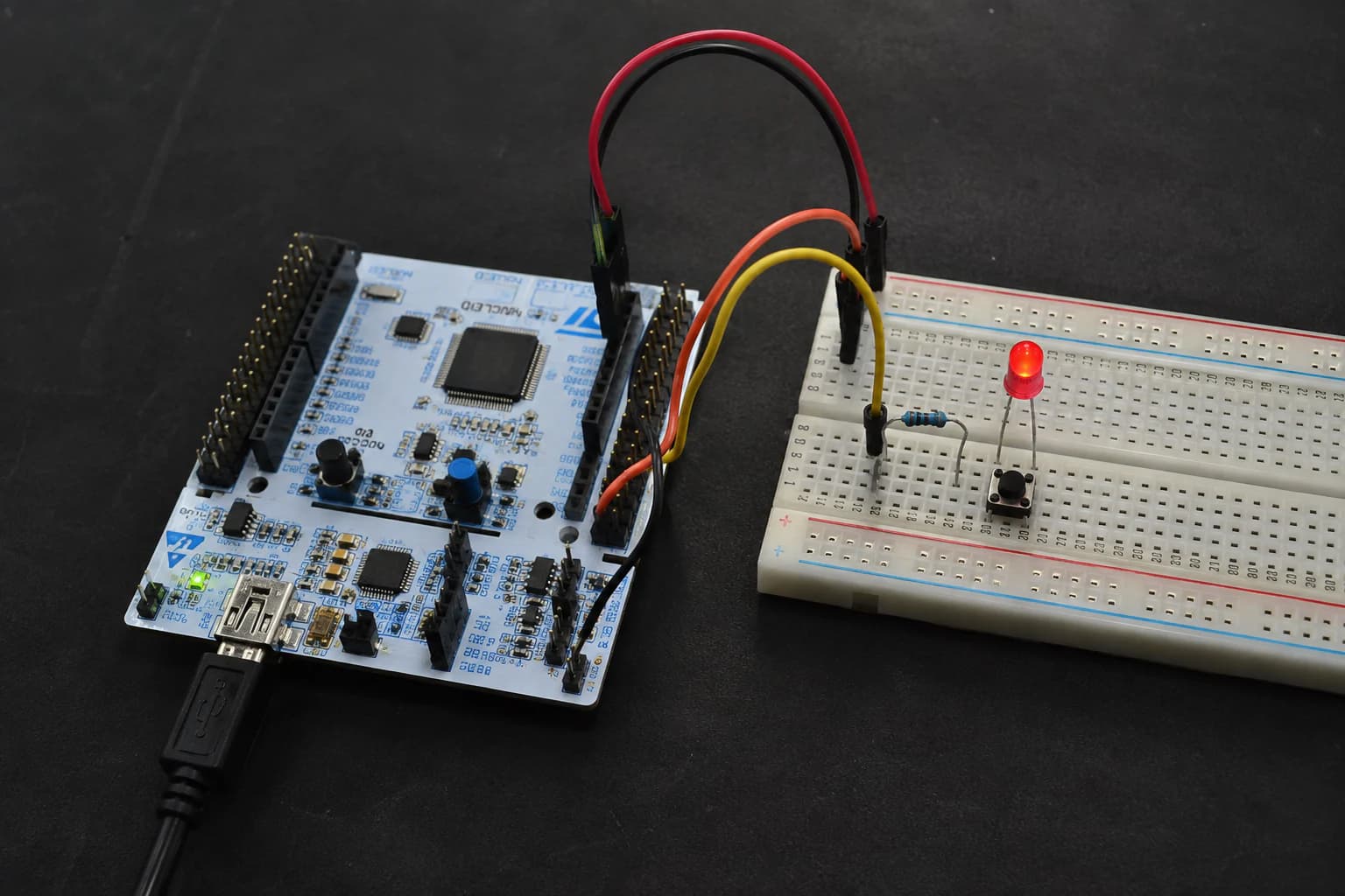
A timer creates a regular time base and is more suitable than HAL_Delay when an application has other work to do.
A timer is a peripheral with a counter driven by a clock. When the counter reaches a configured value, it can create an update event, interrupt, or PWM waveform.
The approximate update-frequency formula is:
f_update = f_timer_clock / ((Prescaler + 1) × (Period + 1))
For example, with a 64 MHz timer clock, an update every 1 ms (1 kHz) can use a prescaler that produces a 1 MHz counter clock and a period of 999:
64 MHz / (64 × 1000) = 1 kHz
This is a calculation example, not a universal configuration. Your clock tree, timer bus, and APB prescaler determine the real f_timer_clock. Check the value generated by CubeMX instead of guessing from the CPU frequency.
Timer interrupt and a periodic flag
In CubeMX, enable a timer base, choose the prescaler and period, enable the TIMx global interrupt in NVIC, and start it with:
HAL_TIM_Base_Start_IT(&htim6);
The update callback can set a flag:
volatile uint8_t timer_event = 0;

void HAL_TIM_PeriodElapsedCallback(TIM_HandleTypeDef *htim)
{
    if (htim->Instance == TIM6)
    {
        timer_event = 1;
    }
}

while (1)
{
    if (timer_event)
    {
        timer_event = 0;
        HAL_GPIO_TogglePin(LED_GPIO_Port, LED_Pin);
    }
}
Unlike HAL_Delay(), the CPU can continue running the rest of while (1) while it waits. If the timer runs every 500 ms, the LED toggles on that schedule without locking the loop for half a second.
SysTick is also a timer time base
Even before you enable a hardware timer, HAL commonly uses SysTick as a 1 ms time base for HAL_Delay() and HAL_GetTick().
Two details follow from this:
- Do not call
HAL_Delay()inside an ISR without understanding the SysTick priority; the ISR can wait for the very time base it is blocking. - If you replace SysTick with another timer as the HAL time base, keep the tick mechanism aligned with the millisecond unit expected by HAL timeouts.
Think of SysTick as the system time base and a general-purpose timer as an application event source.
Combine all three in a small test
A useful first test is:
- One LED changes state every 500 ms from a timer.
- A button interrupt sets an event or toggles a second LED.
- The main loop remains available for UART and sensors in later lessons.
Do not only watch the LED. Set a breakpoint in the callback, inspect htim->Instance, check the input at both logic levels, and use a multimeter or oscilloscope if the timing is wrong.
Common mistakes
The LED stays dark
Check LED polarity, resistor, common ground, and the LED_GPIO_Port/LED_Pin symbols. An onboard LED may also be active-low; check the board schematic.
The button does not trigger an interrupt
Check the GPIO number, GPIO_EXTI mode, NVIC enable, and whether the selected edge matches the pull-up/pull-down circuit.
One press toggles the LED several times
That is almost certainly bounce. Do not raise the interrupt priority; add debounce and accept only one valid event.
The timer is too fast or too slow
Check the clock tree, timer bus, prescaler, period, and whether HAL_TIM_Base_Start_IT() was called. A timer does not start merely because it was configured in CubeMX.
The callback is never reached
Check that the CubeMX-generated interrupt handler calls HAL_GPIO_EXTI_IRQHandler() or HAL_TIM_IRQHandler() for the relevant peripheral. Then verify the callback name for the STM32 family in use.
Conclusion
GPIO lets STM32 interact with digital signals. Interrupts let firmware react to events instead of constantly polling. Timers create a regular time base so an application can work on schedule without relying on blocking delays.
If you remember only three things:
- GPIO configuration must match the real circuit, especially pull resistors and active-low logic.
- Keep ISRs short; record events and do heavier work in the main loop.
- Timers are not only for blinking LEDs. They are the foundation for sampling, timeouts, debounce, and simple scheduling.
In P3: UART, I2C, and SPI, I will use UART to debug firmware and read STM32 data on the computer. Once you can see logs, GPIO, interrupt, and timer bugs become much less of a guessing game.
References and open-source projects
- STMicroelectronics/STM32CubeG0 — GPIO_EXTI example — HAL EXTI example and callback handling.
- STMicroelectronics/STM32CubeG0 — Projects list — GPIO, EXTI, TIM, and board-specific examples.
- STM32CubeG0 getting started guide — official STM32CubeG0 package guide.
- STM32-base/STM32-base-STM32Cube — community repository bundling official CMSIS and HAL sources for reference.
Share
Keep exploring
Read next
Related articles
STM32 Beginner - P3: UART, I2C, and SPI with HAL
Learn the three common STM32 interfaces: use UART for debugging, I2C for sensors, and SPI for displays or memory with STM32CubeIDE and HAL.
STM32 Beginner - Part 5: Building a Complete Application
Combine timer, ADC, DMA, PWM, I2C, and UART into a small STM32 bench monitor with a clear firmware architecture, fault handling, and room to grow into a real project.
STM32 Beginner Guide P4: ADC, PWM, and DMA from Analog to Continuous Data
Learn to read analog signals with ADC, control LED brightness with PWM, and transfer multiple samples through DMA on STM32CubeIDE using HAL.