

STM32 Beginner Guide P4: ADC, PWM, and DMA from Analog to Continuous Data
Learn to read analog signals with ADC, control LED brightness with PWM, and transfer multiple samples through DMA on STM32CubeIDE using HAL.
Share
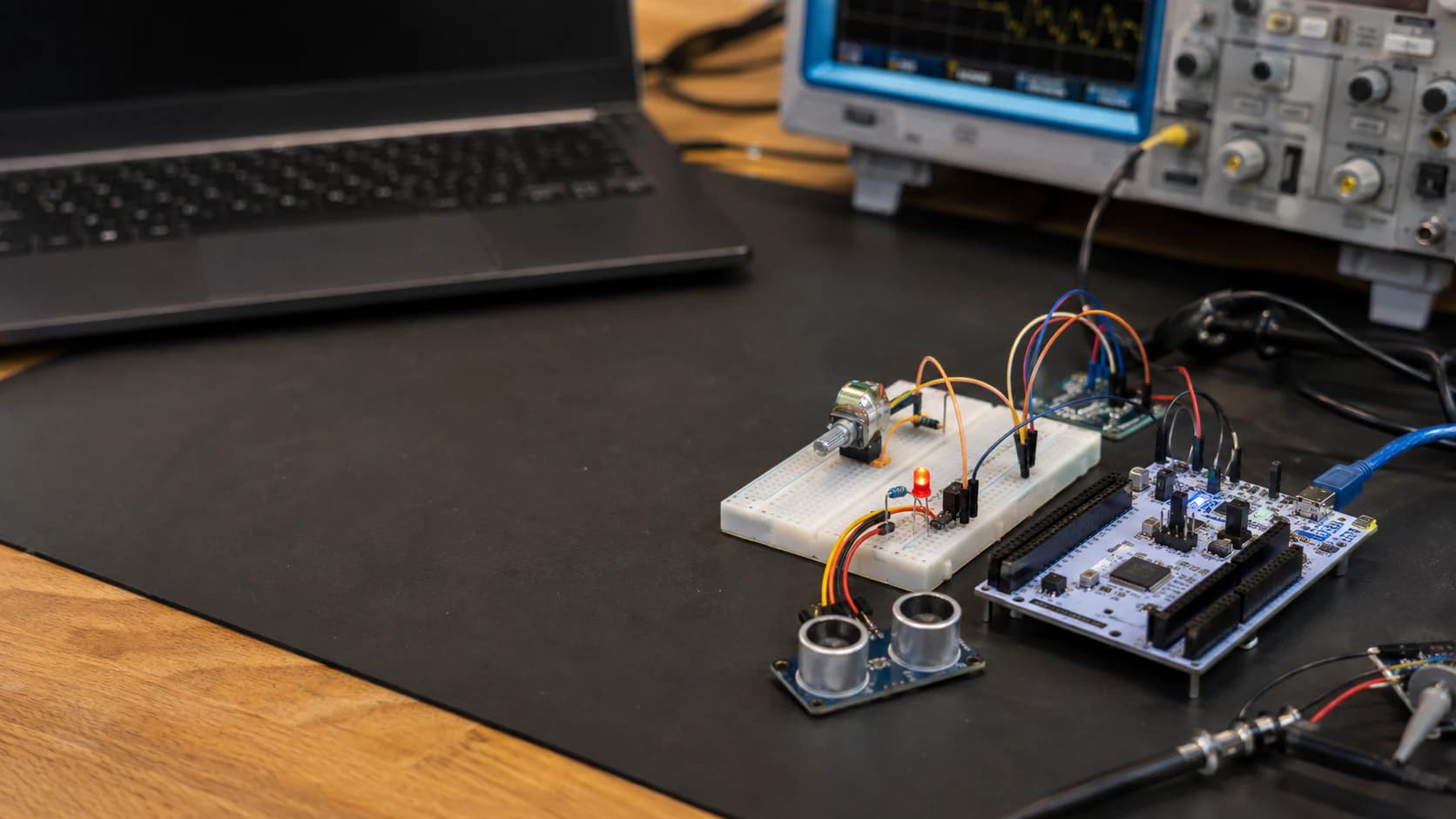
In P3: UART, I2C, and SPI, I used serial interfaces to talk to a laptop, sensor, and display. P4 moves to three peripherals that help firmware work with analog signals, controlled power, and larger data streams.
Series: P1: Getting Started with STM32 · P2: GPIO, Interrupts, and Timers · P3: UART, I2C, and SPI · P4 is here
I will increase the complexity gradually:
- Read a potentiometer with ADC.
- Use that value to change LED brightness with PWM.
- Capture many ADC samples into a buffer with DMA.
The examples continue with NUCLEO-G071RB, STM32CubeIDE, and HAL. ST provides ADC, timer/PWM, and DMA examples in STM32CubeG0; I will keep the code easy to measure and debug before optimizing it.
ADC: turn voltage into digital data
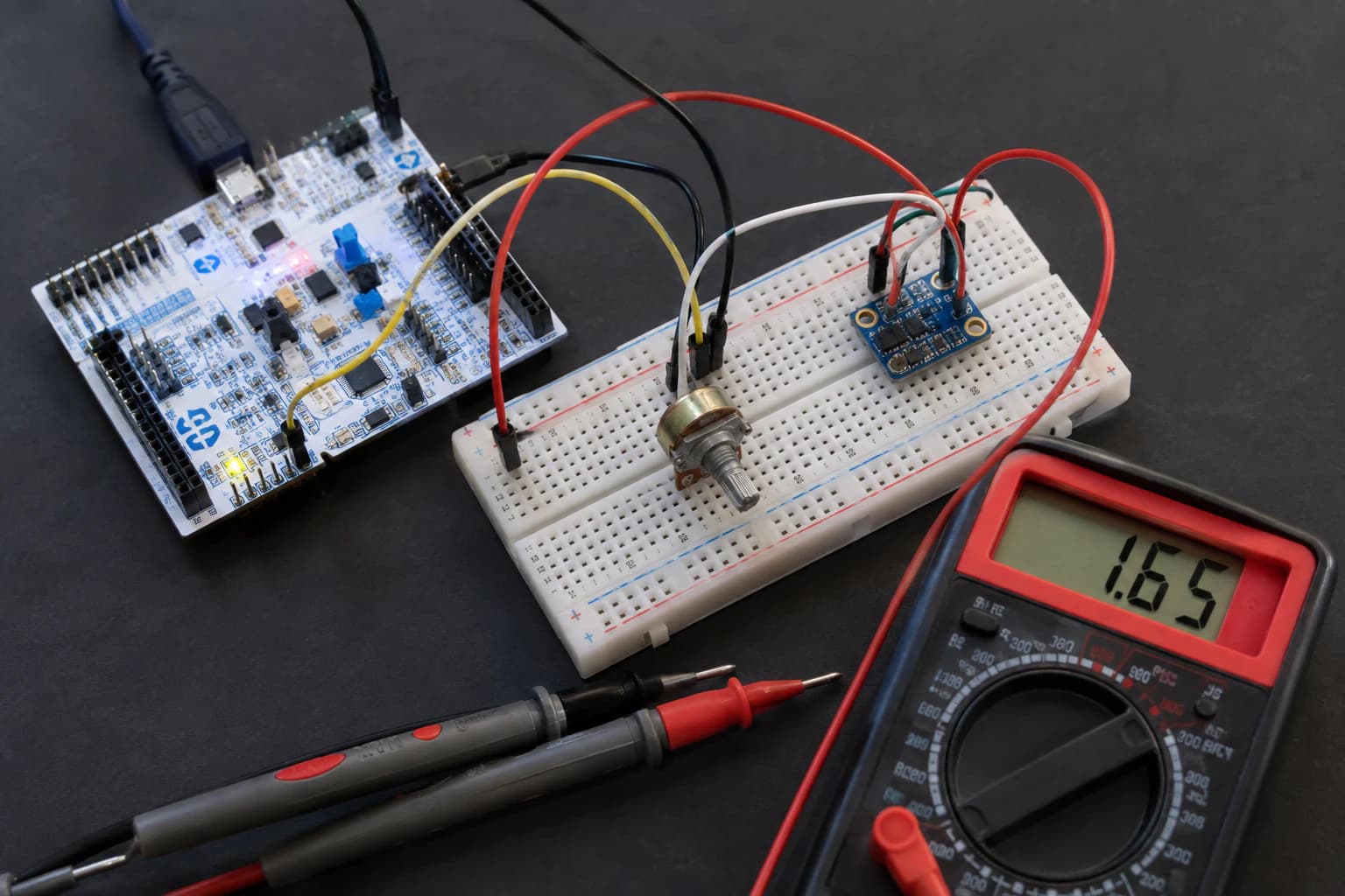
An ADC turns analog voltage into a number; reference, source impedance, and noise all affect the result.
An ADC, or Analog-to-Digital Converter, samples an analog voltage and represents it as an integer. A 12-bit ADC has 2^12 = 4096 levels, from 0 to 4095.
Assuming a 3.3 V reference, the ideal calculation is:
voltage = adc_value × 3.3 / 4095
That is only an ideal model. The real reference voltage, ADC linearity, supply noise, source impedance, and sampling time all affect the reading.
Wire a potentiometer
For a 10 kΩ potentiometer, connect the two outer terminals to 3V3 and GND, and the wiper to an ADC pin:
3V3 ---- potentiometer ---- GND
                 |
                 +---------- ADC input
Never feed a voltage above the ADC pin's limit into the input. If an analog source can exceed 3.3 V, use a divider and recalculate the measurement range.
In CubeMX, choose a pin with an ADC function, enable its channel, and start with the default resolution. Do not select a pin only because its header label looks like A0; check the alternate function for the exact MCU and board.
Read ADC with polling
Assuming CubeMX generated hadc1 and configured its channel:
uint32_t adc_value = 0;

HAL_ADC_Start(&hadc1);

if (HAL_ADC_PollForConversion(&hadc1, 100) == HAL_OK)
{
    adc_value = HAL_ADC_GetValue(&hadc1);
}

HAL_ADC_Stop(&hadc1);
This is the clearest first reading. HAL_ADC_PollForConversion() waits for the conversion to finish, so do not call it in a tight loop at high speed without a timing plan.
To convert the result to millivolts:
uint32_t millivolts = (adc_value * 3300U) / 4095U;
This value is only relatively meaningful until you calibrate and verify VREF+. For an accuracy-sensitive product, read the calibration information and datasheet for the exact STM32 family.
Why does ADC become noisy?
These are the causes I usually check:
- Long analog wires routed near clock or PWM signals.
- Analog power or ground sharing a return path with a large load.
- A high-impedance source with too-short sampling time.
- Trusting one sample immediately.
- An LED or motor switching while the ADC samples.
Reading multiple samples and averaging them reduces some random noise:
uint32_t sum = 0;

for (uint32_t i = 0; i < 16; i++)
{
    HAL_ADC_Start(&hadc1);
    HAL_ADC_PollForConversion(&hadc1, 100);
    sum += HAL_ADC_GetValue(&hadc1);
    HAL_ADC_Stop(&hadc1);
}

uint32_t average = sum / 16U;
Oversampling does not fix a wrong pin, wrong reference, or systematic noise. It only helps with part of the random noise.
PWM: control with duty cycle
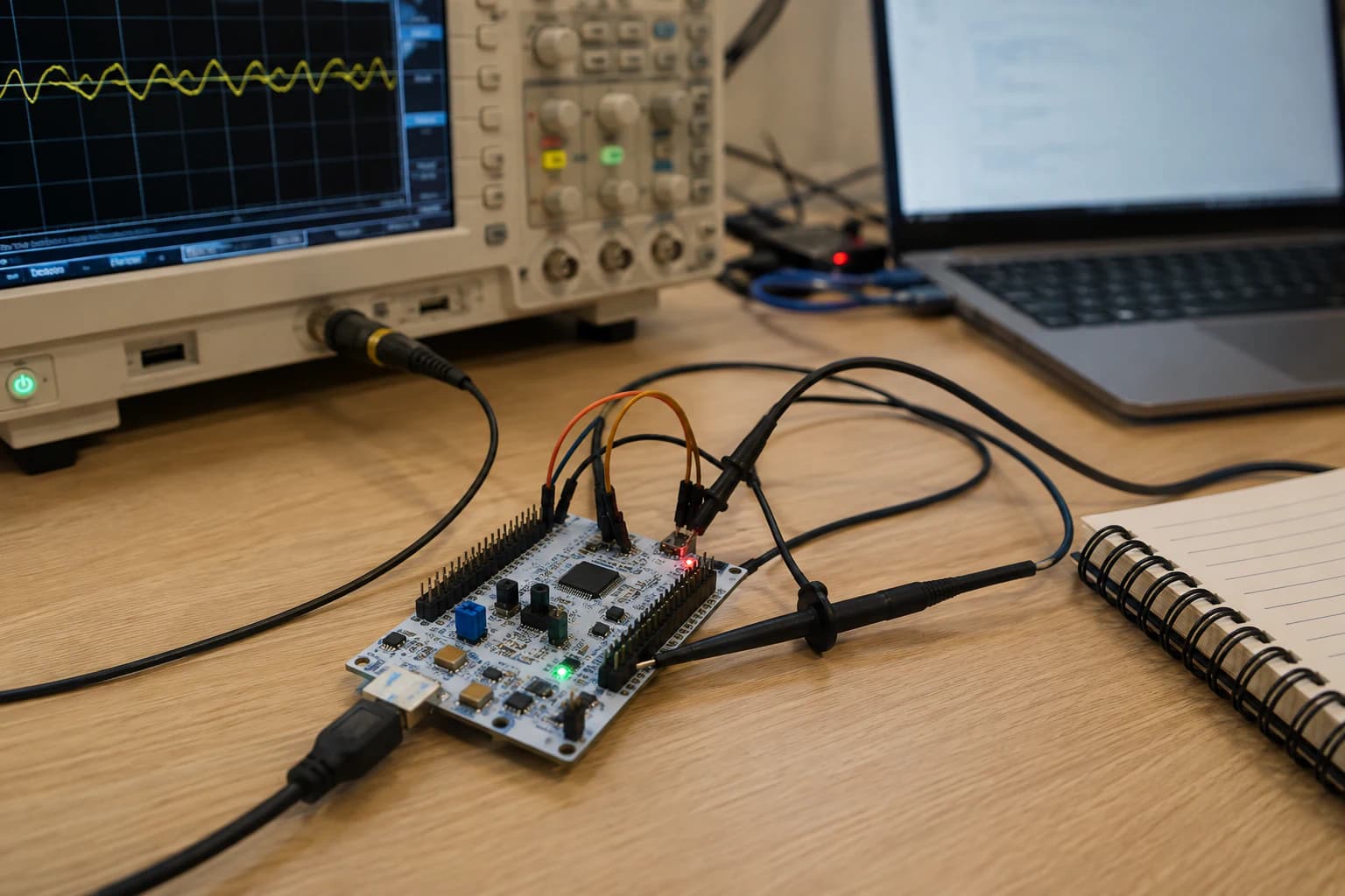
PWM does not create a real analog voltage; it changes the duty cycle of a digital pulse to control average power.
PWM, or Pulse-Width Modulation, switches a digital signal on and off at a fixed frequency. Duty cycle is the fraction of each period for which the signal is HIGH.
duty cycle = HIGH time / period
With an LED, human vision integrates light over time, so a smaller duty cycle usually looks dimmer. With a motor or heater, duty cycle can control average power, but the load still needs a suitable driver circuit.
PWM does not turn a GPIO into a clean analog source. A real analog voltage needs a DAC or an appropriate filter and must be checked against the load.
Configure PWM in CubeMX
Choose a timer channel with a PWM alternate function, set it to PWM Generation CHx, and configure:
- Prescaler to create the counter frequency.
Periodto set the duty resolution.Pulseas the initial compare value.- Polarity for the load.
For example, with Period = 999, a compare value from 0 to 999 gives an approximately 0–100% duty range:
uint32_t duty = 500;
__HAL_TIM_SET_COMPARE(&htim3, TIM_CHANNEL_1, duty);
Do not call HAL_TIM_PWM_Start() on every update. Start it once after initialization, then change only the compare value:
HAL_TIM_PWM_Start(&htim3, TIM_CHANNEL_1);

while (1)
{
    uint32_t duty = (adc_value * 999U) / 4095U;
    __HAL_TIM_SET_COMPARE(&htim3, TIM_CHANNEL_1, duty);
}
In real code, clamp the range and update from a timer/event instead of running an uncontrolled tight loop.
How do you choose the PWM frequency?
Too low can make an LED flicker or a motor vibrate. Too high reduces duty resolution, increases switching loss, or exceeds the driver limit.
The formula depends on the timer clock:
f_pwm = f_timer_clock / ((Prescaler + 1) × (Period + 1))
For an LED, a few hundred hertz to a few kilohertz is a reasonable test range. For motors, fans, audio, or switching supplies, choose from the datasheet and system requirements instead of applying one value everywhere.
DMA: let the peripheral move data for you
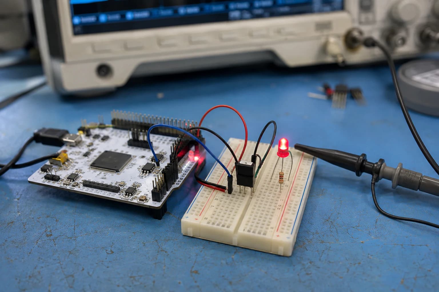
DMA moves blocks of data between a peripheral and RAM so the CPU can do other work while the transfer runs.
DMA, or Direct Memory Access, lets a peripheral transfer data to or from RAM through a buffer. The CPU configures the transfer, continues other work, and receives an interrupt when the transfer completes or reaches the halfway point.
Without DMA, a long ADC sample sequence usually repeats this work:
- Start a conversion.
- Wait for completion.
- Read the data register.
- Store the value in an array.
- Repeat hundreds or thousands of times.
DMA can perform that repetition automatically. This is why it helps with ADC sampling, UART streams, SPI displays, audio, and peripherals producing regular data.
ADC + DMA in a block
Create a buffer:
#define ADC_BUFFER_LENGTH 64

uint16_t adc_buffer[ADC_BUFFER_LENGTH];
In CubeMX, enable DMA for the ADC, choose peripheral-to-memory, enable memory increment, and use circular mode for continuous sampling. Then start it:
HAL_ADC_Start_DMA(&hadc1,
                  (uint32_t *)adc_buffer,
                  ADC_BUFFER_LENGTH);
When the buffer is full, a callback can notify the application:
volatile uint8_t adc_block_ready = 0;

void HAL_ADC_ConvCpltCallback(ADC_HandleTypeDef *hadc)
{
    if (hadc->Instance == ADC1)
    {
        adc_block_ready = 1;
    }
}
The main loop processes the block:
while (1)
{
    if (adc_block_ready)
    {
        adc_block_ready = 0;

        uint32_t sum = 0;
        for (uint32_t i = 0; i < ADC_BUFFER_LENGTH; i++)
        {
            sum += adc_buffer[i];
        }

        uint32_t average = sum / ADC_BUFFER_LENGTH;
        // Use average to control PWM or send over UART
    }
}
The callback should only record state. Avoid averaging 64 samples, formatting a string, and sending a long UART message inside the callback unless there is a specific reason.
Circular DMA and half-transfer
In circular mode, DMA returns to the beginning after reaching the end. For a continuous stream, process the first half when DMA reaches halfway and the second half when the buffer is full:
void HAL_ADC_ConvHalfCpltCallback(ADC_HandleTypeDef *hadc)
{
    if (hadc->Instance == ADC1)
    {
        // Process or mark the first half of the buffer
    }
}
The CPU must finish processing one half before DMA writes over that half again. If processing is too slow, you lose samples even though ADC and DMA still appear to be running.
DMA is not free
DMA reduces the number of data copies handled by the CPU, but you still need:
- A buffer in RAM accessible by DMA.
- Data width and transfer length matching the peripheral.
- No reading of a buffer while DMA is writing the same region without synchronization.
- Correct error handling and a clean stop sequence.
- Cache coherency checks on MCUs with data cache.
On STM32G0 and this simple example, cache is usually not the main concern. But learning to think about buffer ownership early will help when you move to STM32F7, H7, or a system with several streams.
Combine ADC, PWM, and DMA
A small pipeline can look like this:
Timer trigger -> ADC sample -> DMA buffer -> main loop processing -> PWM compare
In a simple demo, take the average of adc_buffer, scale it from the ADC range to the PWM compare range, and update CCR:
uint32_t pwm_compare = (average * PWM_PERIOD) / ADC_MAX_VALUE;

if (pwm_compare > PWM_PERIOD)
{
    pwm_compare = PWM_PERIOD;
}

__HAL_TIM_SET_COMPARE(&htim3, TIM_CHANNEL_1, pwm_compare);
A timer trigger makes the distance between samples more consistent than starting conversions at arbitrary points in the main loop. This is the first step from an LED demo toward a data logger or a controller with stable timing.
Common mistakes
ADC is always zero or full scale
Check that the pin is actually an ADC channel, the potentiometer connects to 3V3/GND, ground is shared, and the input is not shorted. A wrong channel in CubeMX can look exactly like broken hardware.
ADC becomes noisy when PWM runs
Lower the PWM frequency, move the analog wiring, improve ground and decoupling, increase sampling time, and average more samples. If the noise comes from the LED or motor return current, layout will help more than adding a software filter alone.
PWM has no output
Check the timer channel, GPIO alternate function, HAL_TIM_PWM_Start(), and whether another peripheral owns the pin. On a Nucleo, verify that you are probing the correct header pin rather than a different connector position.
PWM frequency is right but duty is wrong
Check Period, compare value, polarity, and scaling limits. Pulse is not always a percentage; it is a compare count within the timer period.
The DMA callback never runs
Check the DMA request and channel, NVIC, interrupt handler, and whether HAL_ADC_Start_DMA() was called. If it runs once and stops, check normal/circular mode and ADC/DMA error flags.
The DMA buffer contains stale data or is overwritten
Do not process a region while DMA is writing it. Use half/full callbacks, a double buffer, or explicit buffer ownership. This is a synchronization problem, not merely a data-type problem.
Conclusion
ADC lets STM32 read the analog world. PWM turns a timer into a tool for controlling average power. DMA lets peripherals move block data without asking the CPU to handle every sample.
If you are new to this, follow the sequence: read one ADC sample with polling, create a fixed PWM output, connect ADC to PWM, and only then enable DMA. Verify each step with a multimeter, oscilloscope, or UART before adding the next one.
In P5, I will combine the pieces into a small application: a timer triggers sampling, DMA collects data, UART prints status, and a PWM output responds to the measured value.
References and open-source projects
- STMicroelectronics/STM32CubeG0 — official firmware package with HAL, LL, BSP, and peripheral examples.
- STM32CubeG0 Projects list — ADC, TIM, DMA, and board-specific examples.
- Getting started with STM32CubeG0 — official guide to package structure and transfer styles.
- STM32-base/STM32-base-STM32Cube — community repository bundling official CMSIS and HAL sources for reference.
Share
Keep exploring
Read next
Related articles
STM32 Beginner - P3: UART, I2C, and SPI with HAL
Learn the three common STM32 interfaces: use UART for debugging, I2C for sensors, and SPI for displays or memory with STM32CubeIDE and HAL.
STM32 Beginner - Part 5: Building a Complete Application
Combine timer, ADC, DMA, PWM, I2C, and UART into a small STM32 bench monitor with a clear firmware architecture, fault handling, and room to grow into a real project.
STM32 Beginner Guide P2: GPIO, Interrupts, and Timers from the First Example
Learn to configure GPIO, capture a button event with an EXTI interrupt, and create a periodic time base with a timer on STM32CubeIDE using a NUCLEO-G071RB board.