

STM32 Beginner - Part 5: Building a Complete Application
Combine timer, ADC, DMA, PWM, I2C, and UART into a small STM32 bench monitor with a clear firmware architecture, fault handling, and room to grow into a real project.
Share
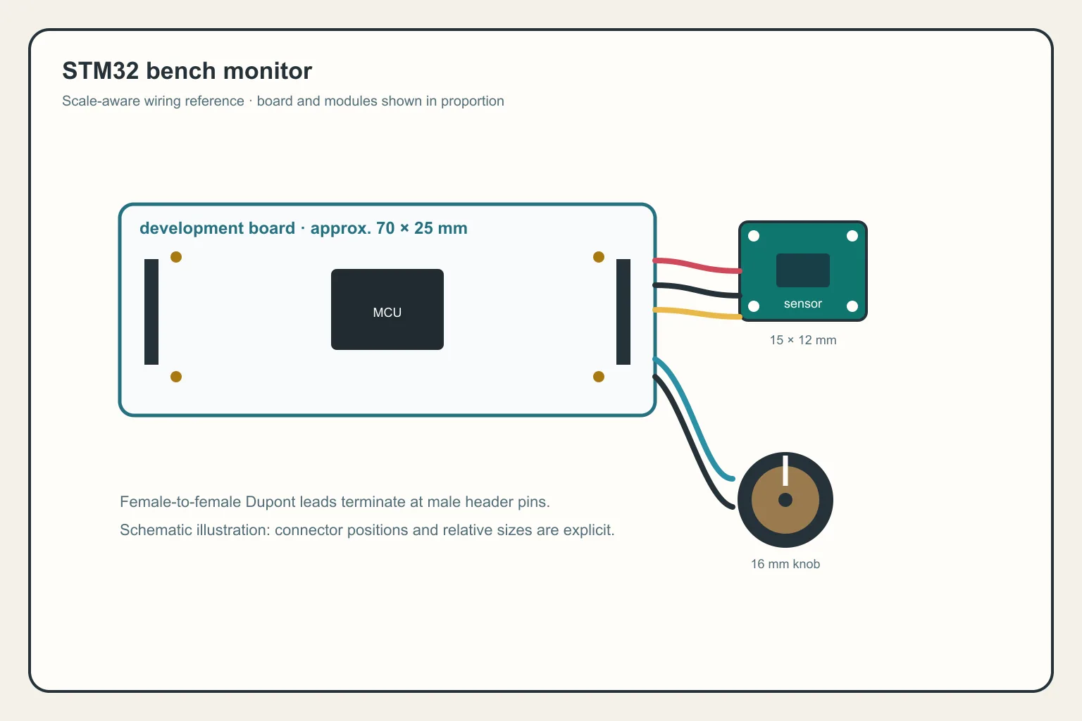
This is the final part of the STM32 Beginner Guide. In P4: ADC, PWM, and DMA, I studied each peripheral separately. Real firmware rarely uses only one peripheral, though. The more useful question is how to combine them into a system with a clear schedule, useful logs, and a plan for when hardware stops responding.
Series: P1: Getting Started with STM32 · P2: GPIO, Interrupts, and Timers · P3: UART, I2C, and SPI · P4: ADC, PWM, and DMA · P5 is here
In this article, I will build a STM32 Bench Monitor. It is a small learning application, not a finished product:
- A timer creates the sampling rhythm.
- ADC reads a potentiometer or analog signal.
- DMA moves samples into a buffer.
- I2C reads an environmental sensor.
- PWM controls an indicator LED.
- UART sends structured logs to the computer.
The reference board remains NUCLEO-G071RB, with STM32CubeIDE and HAL. Peripheral names, channels, and pins can differ on another board, so treat the code below as an architecture and compare it with the generated code in your own project.
What does a complete application need to solve?
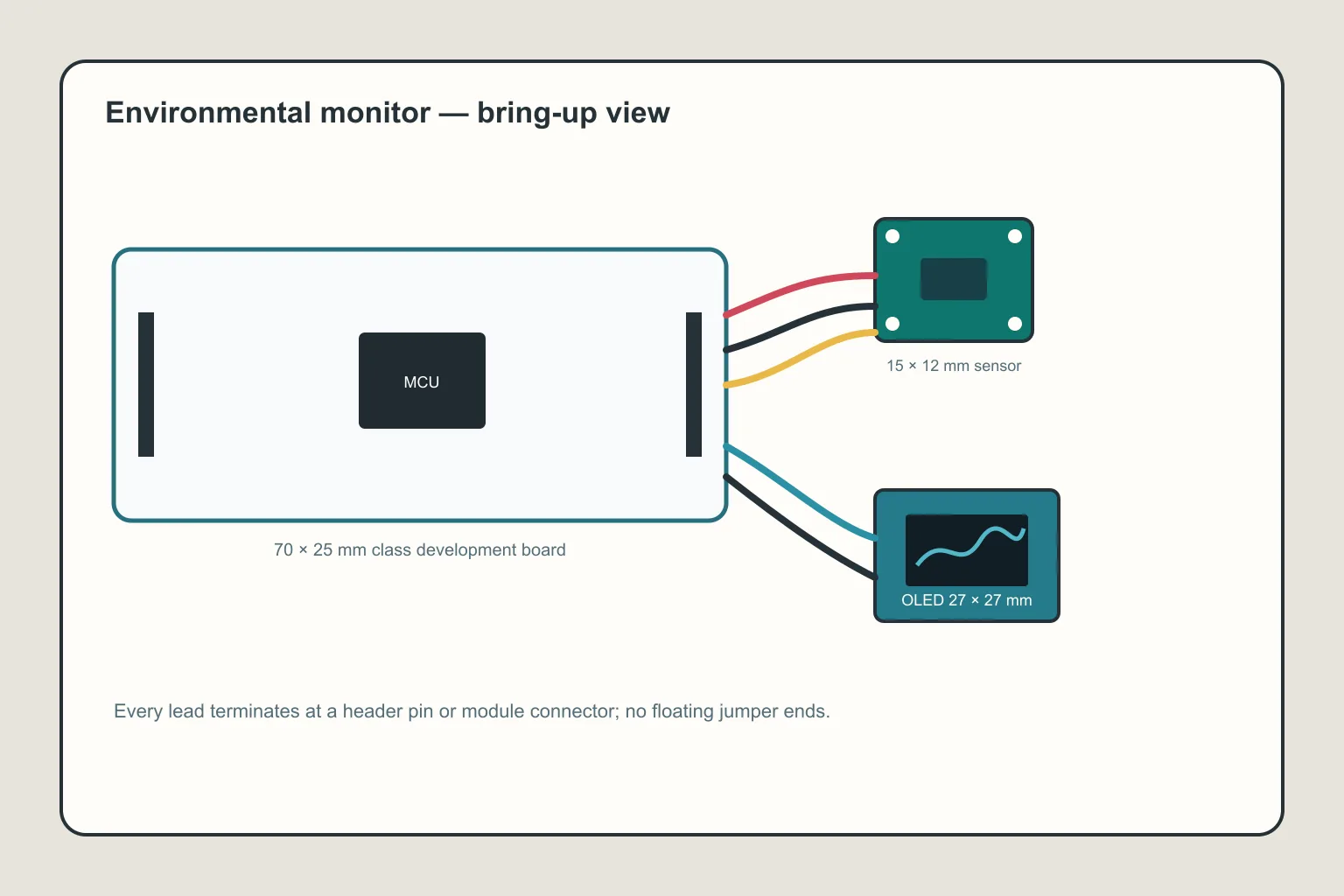
A complete application does not need to be large; each peripheral simply needs a clear role.
A blinking LED only proves that one output works. An application needs to answer a few more questions:
- When is data sampled?
- Which peripheral owns the buffer at each moment?
- What happens when the sensor times out?
- Does the log contain enough information to debug the system?
- Can one slow operation stop everything else?
I will use a simple rule: interrupts and DMA report events; the main loop makes decisions and performs heavier work.
Architecture at a glance
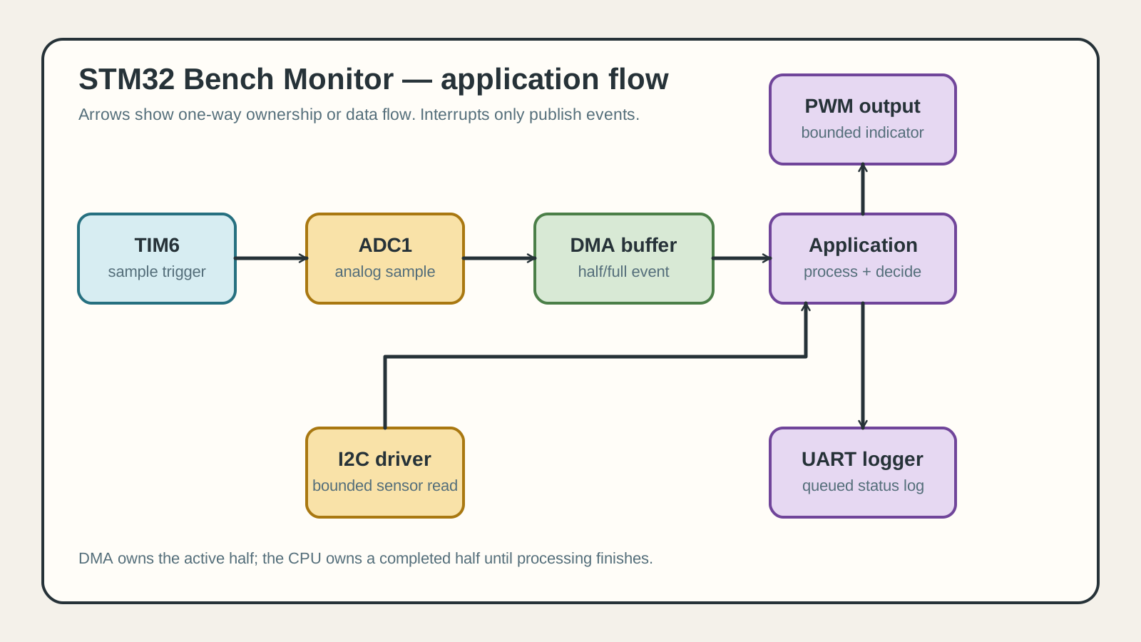
The application layer coordinates events while each driver owns one hardware interface.
The main data flow is:
TIM6 trigger -> ADC1 -> DMA buffer -> main loop -> PWM + UART
                              ^
                              |
                       I2C sensor read
The timer does not “do everything”. It creates a regular rhythm. ADC samples on that rhythm. DMA moves the samples. When a block is ready, a callback sets a flag. The main loop processes the block, reads the sensor on its own schedule, and updates the outputs.
Give each module one job
| Module | Responsibility | Should not do |
|---|---|---|
app_scheduler | Receive events and decide what runs | Put every driver in one file |
adc_stream | Manage ADC and DMA buffers | Format logs or control the UI |
sensor | Read I2C and return data/error | Wait forever when the sensor is gone |
indicator | Scale data into PWM | Know ADC register details |
logger | Send a consistent UART format | Print long logs inside an ISR |
This is not a large architecture framework. It is just enough separation to replace a BME280 with another sensor or replace an LED with a motor driver without breaking everything around it.
Keep the driver and application layers separate
The driver layer knows about HAL handles, registers, addresses, and electrical details. The application layer knows about measurements, schedules, policy, and safe behavior. A small project can reflect that boundary in its files:
Core/
  Inc/app_monitor.h       application state and public events
  Src/app_monitor.c       main-loop orchestration and fault policy
Drivers/
  adc_stream.c/.h         ADC + DMA block ownership
  environment_sensor.c/.h I2C transaction and sensor decoding
  indicator.c/.h           bounded PWM output
  logger.c/.h              UART queue and log formatting
For example, environment_sensor_read() may return SENSOR_TIMEOUT, SENSOR_BUS_ERROR, or SENSOR_OK. The application decides whether to retry, mark the sample invalid, or enter a safe state; the driver should not decide product policy. Keep CubeMX-generated initialization in its own area and put application logic in user files so regeneration does not erase it.
Configure CubeMX
For a NUCLEO-G071RB project, configure:
- A base timer such as
TIM6to create periodic update events. - An ADC channel, optionally triggered by the timer for consistent sample intervals.
- ADC DMA, peripheral-to-memory, memory increment, and circular mode.
- A PWM timer channel such as
TIM3_CH1according to the real pin mapping. - One I2C instance for the sensor.
- One UART/USART for logs.
- NVIC for DMA, timer, and any peripheral using interrupts.
The names TIM6, ADC1, TIM3_CH1, and I2C1 are illustrative. CubeMX pin mapping may require different instances. Do not edit handle names by hand before understanding the .ioc file and generated code.
Step 1: define the minimum state
I start with explicit state instead of scattering unnamed global variables everywhere:
#define ADC_BUFFER_LENGTH 64U
#define ADC_MAX_VALUE     4095U
#define PWM_PERIOD         999U

static uint16_t adc_buffer[ADC_BUFFER_LENGTH];

static volatile uint8_t adc_half_ready = 0U;
static volatile uint8_t adc_full_ready = 0U;
static volatile uint8_t sensor_due = 0U;
static volatile uint8_t logger_due = 0U;

typedef enum
{
    SENSOR_OK,
    SENSOR_TIMEOUT,
    SENSOR_BUS_ERROR
} sensor_status_t;

typedef enum
{
    APP_STARTING,
    APP_RUNNING,
    APP_DEGRADED,
    APP_FAULT
} app_state_t;

typedef struct
{
    uint16_t analog_average;
    int32_t temperature_milli_c;
    uint8_t sensor_valid;
    sensor_status_t sensor_error;
    uint32_t sensor_failures;
    app_state_t state;
    uint32_t sequence;
} monitor_state_t;

static monitor_state_t monitor = {0};
Use volatile only for values changed in an interrupt and read in the main loop. It does not make a multi-variable update atomic. When state becomes more complex, define ownership or a critical section explicitly.
Step 2: start peripherals in order
After the CubeMX-generated MX_*_Init() functions, the application can start its peripherals:
HAL_ADC_Start_DMA(&hadc1,
                  (uint32_t *)adc_buffer,
                  ADC_BUFFER_LENGTH);

HAL_TIM_PWM_Start(&htim3, TIM_CHANNEL_1);

HAL_TIM_Base_Start_IT(&htim6);
In a real project, check the return value of every call. If a peripheral cannot start, enter a clear fault state instead of continuing as if everything were fine.
Order matters too. DMA must be ready before ADC produces a stream. PWM should be in a safe state before the application drives a load. Start the timer trigger after the receive path is ready.
Step 3: callbacks only signal events
ADC reports ownership of one half of the circular buffer:
void HAL_ADC_ConvHalfCpltCallback(ADC_HandleTypeDef *hadc)
{
    if (hadc->Instance == ADC1)
    {
        adc_half_ready = 1U;
    }
}

void HAL_ADC_ConvCpltCallback(ADC_HandleTypeDef *hadc)
{
    if (hadc->Instance == ADC1)
    {
        adc_full_ready = 1U;
    }
}
The timer schedules slower work:
void HAL_TIM_PeriodElapsedCallback(TIM_HandleTypeDef *htim)
{
    if (htim->Instance == TIM6)
    {
        static uint32_t tick = 0U;
        tick++;

        if ((tick % 100U) == 0U)
        {
            sensor_due = 1U;
        }

        if ((tick % 500U) == 0U)
        {
            logger_due = 1U;
        }
    }
}
This is a simple example, not a precision scheduler. If events can arrive faster than the main loop handles them, a uint8_t flag loses count. Use a counter, queue, or timestamp according to the meaning of the event. The callback must not average samples, call I2C, or print UART text.
Step 4: Process the ADC buffer
The main loop checks the flag and averages the block:
static uint16_t AverageAdcBlock(const uint16_t *block,
                                uint32_t length)
{
    uint32_t sum = 0U;

    for (uint32_t i = 0U; i < length; i++)
    {
        sum += block[i];
    }

    return (uint16_t)(sum / length);
}
The application calls this function for adc_buffer and &adc_buffer[ADC_BUFFER_LENGTH / 2U] only after the corresponding half/full callback. That is the ownership hand-off: DMA owns the active half, while the CPU owns the completed half. The CPU must finish before DMA wraps around and reuses that region. If it cannot, increment an overrun counter and enter a degraded mode instead of silently trusting stale data.
Step 5: Turn ADC into PWM
Once the average is available, scale it into a compare value:
static void UpdateIndicator(void)
{
    uint32_t compare =
        ((uint32_t)monitor.analog_average * PWM_PERIOD)
        / ADC_MAX_VALUE;

    if (compare > PWM_PERIOD)
    {
        compare = PWM_PERIOD;
    }

    __HAL_TIM_SET_COMPARE(&htim3,
                          TIM_CHANNEL_1,
                          compare);
}
For an LED test, a duty cycle that follows the potentiometer is easy to see. For a power load, never connect it directly to a GPIO/PWM pin; use a MOSFET, gate resistor, flyback diode, or suitable driver for the load.
Step 6: Read an I2C sensor
The sensor task runs when its schedule says it is due:
static void ReadEnvironmentSensor(void)
{
    uint8_t data[2] = {0};
    const uint16_t address = (0x76U << 1);

    if (HAL_I2C_Mem_Read(&hi2c1,
                         address,
                         0xFAU,
                         I2C_MEMADD_SIZE_8BIT,
                         data,
                         sizeof(data),
                         50U) == HAL_OK)
    {
        monitor.temperature_milli_c = DecodeTemperature(data);
        monitor.sensor_valid = 1U;
        monitor.sensor_error = SENSOR_OK;
    }
    else
    {
        monitor.sensor_valid = 0U;
        monitor.sensor_error = SENSOR_TIMEOUT;
    }
}
0xFA and DecodeTemperature() are placeholders. Each sensor has its own register map, conversion time, endianness, and formula. In a real project, the sensor driver should hide these details and return a clear value or error code.
Do not retry forever inside the read function. A short timeout and sensor_valid = 0 let the main loop continue, log the error, and retry on the next scheduled cycle.
Step 7: Use structured UART logs
A useful log answers when, which sequence, what data, and whether the sensor is valid:
static void LogMonitorState(void)
{
    char line[128];
    int length = snprintf(
        line,
        sizeof(line),
        "seq=%lu adc=%u temp_mC=%ld sensor=%s\\r\\n",
        (unsigned long)monitor.sequence,
        monitor.analog_average,
        (long)monitor.temperature_milli_c,
        monitor.sensor_valid ? "ok" : "error");

    if ((length > 0) && ((size_t)length < sizeof(line)))
    {
        HAL_UART_Transmit(&huart2,
                          (uint8_t *)line,
                          (uint16_t)length,
                          100U);
    }
}
The length check matters: when snprintf() truncates, its return value is larger than the bytes actually stored. Never pass that larger value to UART. In a product, snprintf() and blocking UART may not fit a high-rate logger. Use a ring buffer, UART interrupt, or DMA instead. For the first application, short blocking logs make the data flow easy to verify.
Step 8: let the main loop coordinate
The application layer can keep the flow like this:
while (1)
{
    if (adc_half_ready != 0U)
    {
        adc_half_ready = 0U;
        monitor.analog_average = AverageAdcBlock(
            &adc_buffer[0], ADC_BUFFER_LENGTH / 2U);
        UpdateIndicator();
        monitor.sequence++;
    }

    if (adc_full_ready != 0U)
    {
        adc_full_ready = 0U;
        monitor.analog_average = AverageAdcBlock(
            &adc_buffer[ADC_BUFFER_LENGTH / 2U], ADC_BUFFER_LENGTH / 2U);
        UpdateIndicator();
        monitor.sequence++;
    }

    if (sensor_due != 0U)
    {
        sensor_due = 0U;
        ReadEnvironmentSensor();
    }

    if (logger_due != 0U)
    {
        logger_due = 0U;
        LogMonitorState();
    }

    if (ApplicationReadyForWatchdog())
    {
        HAL_IWDG_Refresh(&hiwdg);
    }
}
Notice that there is no long HAL_Delay() in the main loop. Each module does a small piece of work and returns. You can add a button, UART command, or watchdog later without rewriting the entire flow.
Error handling: make failure a state, not a print
Every driver call should have a bounded timeout and a result that the application can act on. Keep counters such as i2c_timeout_count, adc_overrun_count, and uart_drop_count; a single sensor_valid flag tells the UI what to show, but counters explain whether the fault is transient or systemic.
static void ApplySafeOutput(void)
{
    __HAL_TIM_SET_COMPARE(&htim3, TIM_CHANNEL_1, 0U);
}

static void HandleSensorResult(sensor_result_t result)
{
    if (result == SENSOR_OK)
    {
        monitor.sensor_failures = 0U;
        return;
    }

    monitor.sensor_failures++;
    monitor.state = (monitor.sensor_failures >= 3U)
        ? APP_DEGRADED : APP_RUNNING;

    if (monitor.sensor_failures >= 10U)
    {
        monitor.state = APP_FAULT;
        ApplySafeOutput();
    }
}
The exact thresholds depend on the device. The important part is that a missing I2C sensor cannot block forever and cannot silently produce a believable old value. Decide whether a stale value is acceptable, expose its age in the log, and make the output policy explicit.
Watchdog: prove that the application is alive
Configure the independent watchdog with a timeout longer than the worst-case healthy loop, including the maximum allowed I2C transaction. Refresh it from the application context only after the required work has made progress. Do not refresh it from a timer ISR or an unrelated callback: those can continue running while the main loop is dead.
During bring-up, log the reset reason at boot and keep a small reset counter in backup registers or non-volatile storage if the product needs post-mortem evidence. A watchdog reset is useful only when the next boot explains what happened.
Test one layer at a time
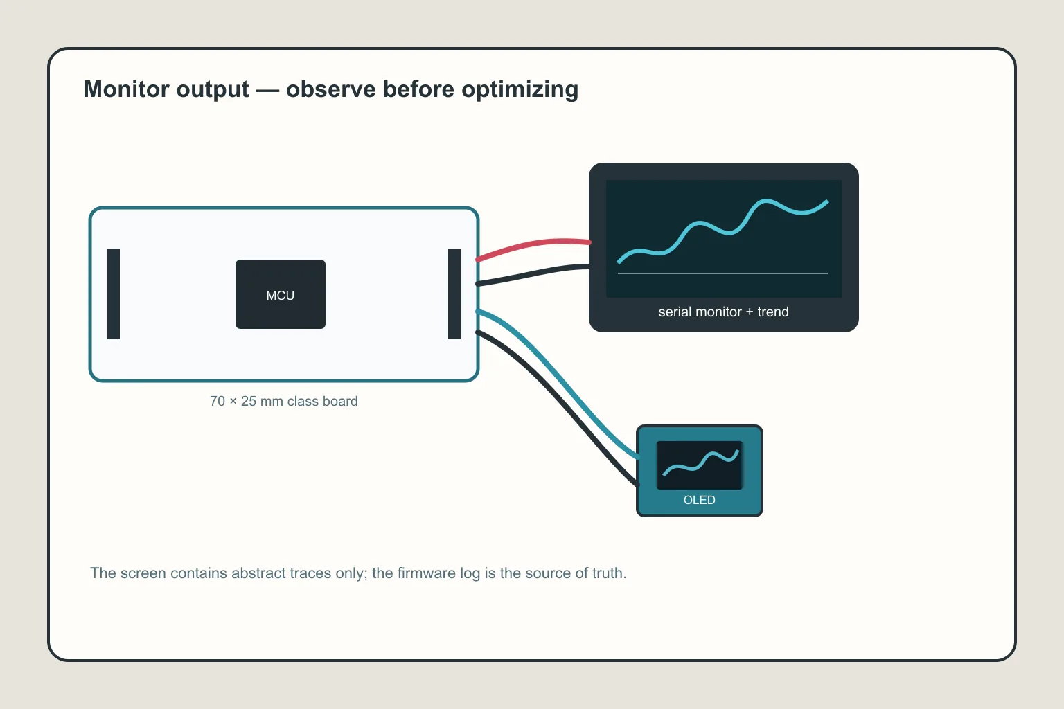
Local logs and status make the system testable before adding a dashboard or cloud connection.
I would not connect every peripheral and run the project once. A less painful sequence is:
- Run ADC polling and confirm the potentiometer changes the value.
- Run fixed PWM and measure its waveform/duty cycle.
- Connect ADC to PWM and verify the minimum/maximum mapping.
- Run I2C
IsDeviceReady, then read a known ID register. - Enable DMA with a small buffer and check the callback.
- Enable the timer trigger and verify sample spacing.
- Add the UART log last so you can observe the whole pipeline.
Each step should have a clear pass condition: ADC average moves from near zero to near full-scale, PWM never exceeds the period, I2C times out within its limit, or DMA never overwrites the region being processed.
Test faults, not only the happy path
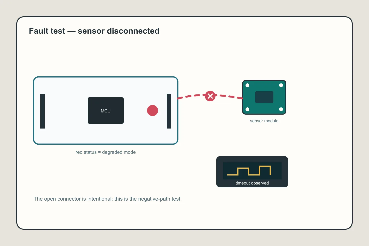
Testing faults such as a missing sensor or timeout is often more valuable than testing only the happy path.
A complete system is defined by what happens when hardware is imperfect. I would test at least:
- Unplug the I2C sensor while the system is running.
- Change the I2C address to the wrong value.
- Keep UART busy or unplug the logging cable.
- Move the ADC input near zero and full-scale.
- Make buffer processing slower than the DMA rate.
- Reset the board during a transaction.
The expected result is not necessarily “no error”. A better result is that the system detects the failure, keeps the output safe, logs the reason, and recovers or requests an intentional reset.
Watchdog and fault state
Once the application has a timer, DMA, I2C, and UART, a watchdog becomes useful. Do not feed it from a timer interrupt regardless of whether the main loop is alive. If the main loop is stuck, the timer may still run and hide the fault.
A simple approach is to refresh the watchdog only after the required tasks complete within a cycle. If a sensor timeout or DMA error persists, enter a FAULT state and decide whether outputs turn off, hold the last value, or use a safe fallback.
Common integration mistakes
The callback runs, but data never changes
Check whether DMA is overwriting the buffer, whether ADC is actually triggered, whether data alignment is correct, and whether the callback belongs to the expected handle.
UART logging causes ADC samples to disappear
HAL_UART_Transmit() can block the main loop for too long. Reduce log frequency, shorten the line, or move the logger to interrupt/DMA mode.
I2C works once and then times out
Check conversion delay, whether the bus is held LOW, pull-ups, and whether the driver starts a new transaction before the previous one has finished.
PWM jitters when it follows ADC
Noisy ADC data makes the duty change constantly. Filter or add hysteresis in the application, reduce hardware noise, and update PWM at a sensible rate.
An event disappears
If a callback sets a flag a second time before the main loop clears it, two events become one. Use a counter or queue when event count matters.
Debug and production-readiness checklist
Before calling the prototype complete, check the system at three levels:
- Observe: measure ADC sample timing and PWM frequency with an oscilloscope, verify I2C ACK/timeout behavior, and capture UART logs with timestamps and reset reason.
- Stress: run for several hours, sweep the analog input, disconnect/reconnect the sensor, fill the logger queue, and deliberately slow block processing to confirm overrun detection.
- Harden: compile with warnings enabled, keep assertions in debug builds, remove secrets and verbose logs from release builds, verify brownout/reset behavior, define safe GPIO states, and record the exact board, clock, pin map, compiler, and firmware version.
For production, replace blocking UART with a bounded queue, add a versioned log format, protect shared state with a documented ownership rule, and test the release binary on real hardware. A clean build is not evidence that timing, electrical limits, and failure recovery are correct.
When should you move to an RTOS?
This application can still run well as a super-loop. You do not need an RTOS merely because there are several peripherals. An RTOS becomes worth considering when tasks have independent timing, need clear blocking/queues, or have more event sources than flags can comfortably coordinate.
Even with an RTOS, the principles remain: short ISRs, clear buffer ownership, bounded timeouts, and intentional fault states.
Conclusion: complete means predictable flow and planned failure
A complete STM32 application does not need a beautiful display or a cloud connection. For me, it needs:
- Inputs sampled on a schedule that can be explained.
- Peripherals coordinated through clear events and buffers.
- Outputs bounded and placed in a safe state.
- Logs that show what the system is doing.
- Communication errors, timeouts, and missing devices handled.
- Code structured so a sensor or output can be replaced without breaking everything.
Across five parts, you moved from choosing a board to a firmware pipeline using GPIO, interrupts, timers, UART, I2C, SPI, ADC, PWM, and DMA. The next step is not to add every remaining peripheral. Build a small project that runs long enough to measure, deliberately create failures, and improve the architecture when its limits become visible.
References and open-source projects
- STMicroelectronics/STM32CubeG0 — official firmware package with HAL, LL, BSP, and board/peripheral examples.
- STM32CubeG0 Projects List — example list and project organization.
- STM32CubeG0 ADC examples — ST ADC examples.
- stm32ai-datalogger — open ST project for logging STM32 data to a computer.
- STM32-base/STM32-base-STM32Cube — community repository bundling official CMSIS and HAL sources for reference.
Share
Keep exploring
Read next
Related articles
STM32 Beginner Guide P1: What Is STM32 and Which Board Should You Choose?
Learn what STM32 is, distinguish chips, modules, and development boards, then choose a practical board for learning GPIO, HAL, STM32CubeIDE, and embedded firmware from the beginning.
STM32 Beginner - P3: UART, I2C, and SPI with HAL
Learn the three common STM32 interfaces: use UART for debugging, I2C for sensors, and SPI for displays or memory with STM32CubeIDE and HAL.
STM32 Beginner Guide P2: GPIO, Interrupts, and Timers from the First Example
Learn to configure GPIO, capture a button event with an EXTI interrupt, and create a periodic time base with a timer on STM32CubeIDE using a NUCLEO-G071RB board.