

STM32 Beginner - P3: UART, I2C, and SPI with HAL
Learn the three common STM32 interfaces: use UART for debugging, I2C for sensors, and SPI for displays or memory with STM32CubeIDE and HAL.
Share
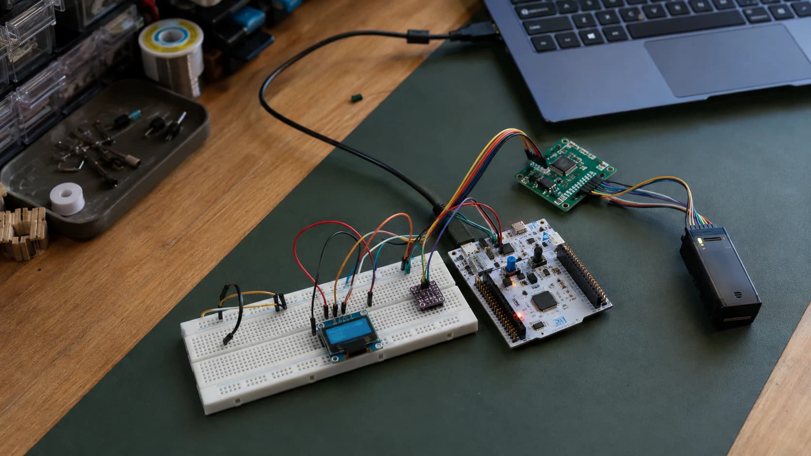
In P2: GPIO, Interrupts, and Timers, I used GPIO, interrupts, and timers to make firmware react to external signals. As soon as a project grows a little, you also need a way to talk to a laptop, sensor, display, or memory chip.
Series: P1: Getting Started with STM32 · P2: GPIO, Interrupts, and Timers · P3 is here
The three interfaces you will see most often in STM32 projects are UART, I2C, and SPI. They all move data serially, but they work in very different ways. Choosing the wrong interface or one misplaced wire can leave firmware apparently running while the external device never answers.
This article continues with NUCLEO-G071RB, STM32CubeIDE, and HAL. ST's official examples are also organized by peripheral and include polling, interrupt, and DMA transfer styles in STM32CubeG0.
Quick view: which interface should you choose?
| Interface | Basic signals | Main strength | Trade-off |
|---|---|---|---|
| UART | TX, RX, GND | Easy debugging and point-to-point links | No shared clock; baud and frame format must match |
| I2C | SDA, SCL, GND | Multiple devices share two signal lines | Needs addresses and pull-ups; usually slower than SPI |
| SPI | SCK, MOSI, MISO, CS, GND | Fast, full-duplex, good for displays/flash | More wires; each device usually needs its own CS |
My practical rule is: UART to see, I2C to ask, SPI to move data quickly. It is not a protocol law, but it is a useful starting point.
Prepare the project in CubeMX
Before writing code, create the project for the exact MCU on the board. Then:
- Select the peripheral under
Connectivity. - Check the pin mapping and alternate functions.
- Choose mode, speed, data size, and interrupt/DMA when needed.
- Use readable handle names such as
huart2,hi2c1, andhspi1. - Generate the code and put custom code inside
USER CODEsections.
Tutorials sometimes use USART and UART as if they were identical. Check the actual peripheral supported by your MCU. A UART without an external clock normally uses only TX and RX; USART also supports synchronous and other modes.
UART: the first serial path for debugging
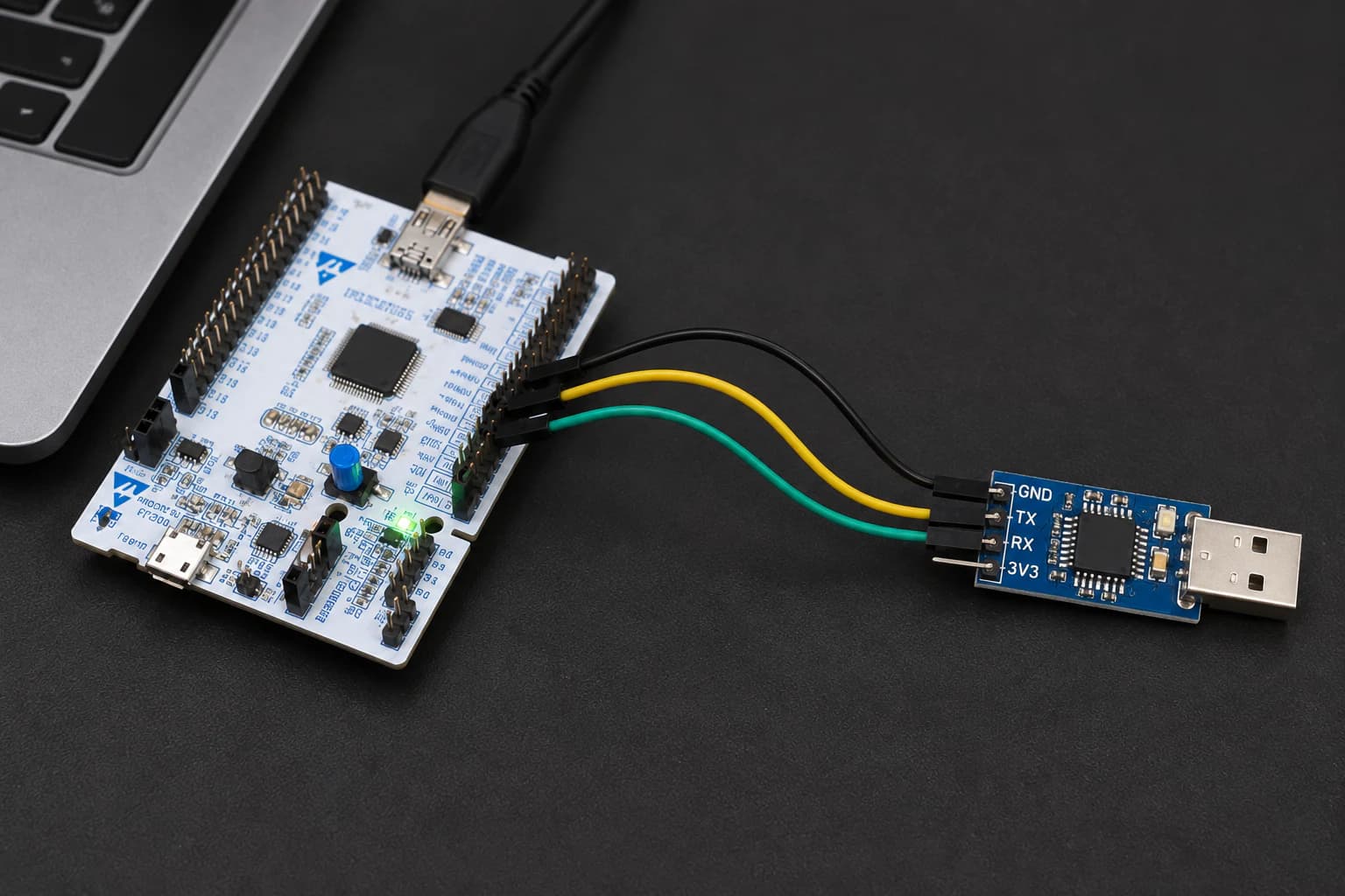
UART is the simplest debugging tool: print what the firmware sees before blaming the sensor.
UART has no shared clock. Both sides must agree on baud rate, data bits, parity, and stop bits. A common configuration is:
115200 baud, 8 data bits, no parity, 1 stop bit
You will often see this written as 115200 8N1.
Wire UART correctly
The minimum UART connection is:
STM32 TX ---- device RX
STM32 RX ---- device TX
STM32 GND --- device GND
TX crosses to RX; TX does not connect to TX. The devices also need a common ground so they share the same voltage reference.
STM32 UART uses the MCU's logic voltage, commonly 3.3 V. Do not connect a real RS-232 port directly to a GPIO; RS-232 uses different voltage levels and polarity and needs a suitable transceiver. Check the logic level of a USB-UART adapter before connecting it.
Transmit with polling
Assuming CubeMX generated huart2, the smallest debug message is:
const char message[] = "hello from STM32\\r\\n";

HAL_UART_Transmit(
    &huart2,
    (uint8_t *)message,
    sizeof(message) - 1,
    100
);
HAL_UART_Transmit() is blocking polling: the CPU waits until the transfer finishes or times out. For short and infrequent logs, it is the clearest approach.
To receive one byte:
uint8_t rx_byte;

if (HAL_UART_Receive(&huart2, &rx_byte, 1, 100) == HAL_OK)
{
    HAL_UART_Transmit(&huart2, &rx_byte, 1, 100);
}
This is an echo example. It is useful for validating baud rate, TX/RX wiring, and terminal settings before adding a protocol.
When should you use interrupts or DMA?
Polling is easy to start with, but it holds the CPU while waiting. For continuous UART traffic, move to:
HAL_UART_Transmit_IT()/HAL_UART_Receive_IT()for small buffers and interrupt-driven handling.HAL_UART_Transmit_DMA()/HAL_UART_Receive_DMA()for longer or higher-rate streams.
Do not start with DMA just because it sounds more professional. Make polling work first, define the frame and timeout, then optimize. UART DMA without a way to detect the end of a frame often moves the problem somewhere else.
I2C: multiple devices on one bus
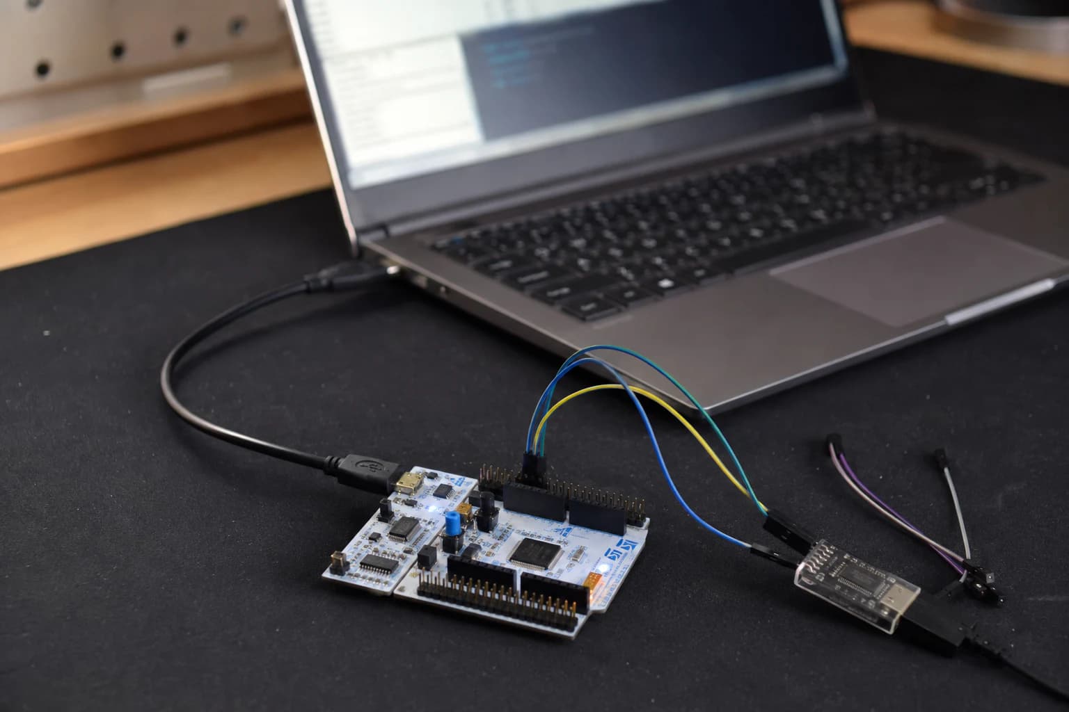
I2C shares two signal lines across devices, but every device must have a distinct address on the bus.
I2C uses two signal lines:
SDA: data.SCL: clock.
Devices share the bus, and the master—usually STM32—generates the clock. Each device has an address so the master can select the intended target.
Pull-ups are required
SDA and SCL are usually open-drain/open-collector lines. Devices pull the line LOW; a pull-up resistor brings it HIGH. The bus therefore needs pull-ups connected to the correct logic rail, usually 3.3 V.
Many sensor breakouts already include pull-ups. If you connect three modules with 4.7 kΩ resistors, the effective pull-up can become lower than expected and increase the LOW-level current. Adding more pull-ups is not always better.
Is the I2C address 7-bit or 8-bit?
Datasheets often show a 7-bit address such as 0x76 or 0x77. Older libraries or documents may show the shifted address byte with the R/W bit. That is why the same sensor sometimes appears with two different values.
With HAL, check the API documentation and the convention used by your driver. Many HAL functions expect the address shifted left by one bit:
uint16_t device_address = 0x76 << 1;
Do not shift it twice. When a device does not respond, this is one of the first checks I make.
Check a device with HAL_I2C_IsDeviceReady.
if (HAL_I2C_IsDeviceReady(&hi2c1, device_address, 3, 100) == HAL_OK)
{
    // The device ACKed the address
}
else
{
    // Check power, ground, SDA, SCL, pull-ups, and address
}
This only tells you that a device responded at that address. It does not prove that timing, register map, or sensor data are correct.
Read and write registers
An I2C sensor usually exposes registers. A generic example is:
uint8_t config = 0x01;
uint8_t data[2];

HAL_I2C_Mem_Write(&hi2c1, device_address, 0x10,
                  I2C_MEMADD_SIZE_8BIT, &config, 1, 100);

HAL_I2C_Mem_Read(&hi2c1, device_address, 0x20,
                 I2C_MEMADD_SIZE_8BIT, data, sizeof(data), 100);
The 0x10 and 0x20 values are only examples. Get the register map and data format from the datasheet for the exact sensor. Reading two bytes does not mean you read the correct temperature; you still need to handle endianness, scaling, signed bits, and data-ready state.
SPI: faster, with more wires
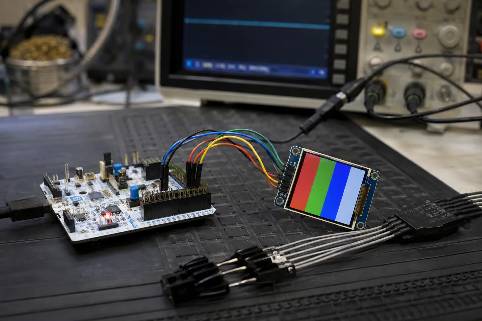
SPI is often faster than I2C, but it needs chip-select and careful checks for mode, bit order, and logic levels.
SPI commonly uses:
SCK: clock generated by the master.MOSI: master out, slave in.MISO: master in, slave out.CSorNSS: selects a slave.GND: common reference.
Each SPI device usually has its own CS. SCK, MOSI, and MISO can be shared when devices are not selected at the same time and the bus is designed accordingly.
Basic SPI configuration
In CubeMX, select master, 2-line full-duplex, 8-bit data, MSB first, and the CPOL/CPHA combination required by the slave datasheet. The four clock modes are:
| Mode | CPOL | CPHA |
|---|---|---|
| 0 | 0 | 0 |
| 1 | 0 | 1 |
| 2 | 1 | 0 |
| 3 | 1 | 1 |
Do not guess the mode from the phrase “SPI display”. Two SPI modules can require different modes.
CS is often controlled by firmware
For many devices, CS is an ordinary GPIO:
HAL_GPIO_WritePin(SPI_CS_GPIO_Port, SPI_CS_Pin, GPIO_PIN_RESET);

HAL_SPI_Transmit(&hspi1, tx_buffer, tx_length, 100);

HAL_GPIO_WritePin(SPI_CS_GPIO_Port, SPI_CS_Pin, GPIO_PIN_SET);
Keep CS LOW for the complete transaction required by the device. Some devices require CS HIGH between command and data; others do not. Read the timing diagram.
SPI can transmit and receive at the same time:
HAL_SPI_TransmitReceive(&hspi1, tx_buffer, rx_buffer, length, 100);
For a write-only display, MISO may not need to be connected. For flash or a sensor that must be read, MISO is required.
Polling, interrupt, or DMA?
STM32CubeG0 includes examples for several transfer styles. I usually choose like this:
| Transfer style | Use it when | Watch out for |
|---|---|---|
| Polling | Initial setup and short transactions | CPU is blocked while waiting |
| Interrupt | The main loop should continue, medium buffers | Clear state machine and callbacks are needed |
| DMA | Long buffers, high frequency, displays/audio | Buffer ownership and completion timing |
Do not start another transaction on the same peripheral before the previous one has finished. With interrupt/DMA, check HAL_BUSY, completion callbacks, and error callbacks before starting the next transfer.
My communication debugging workflow
When a sensor or display does not respond, I use this order:
- Check power and ground with a multimeter.
- Check logic levels: does the device accept 3.3 V?
- Re-read the CubeMX pin mapping and schematic.
- Lower the UART baud, I2C speed, or SPI clock.
- For UART, check crossed TX/RX and
8N1settings. - For I2C, check pull-ups and scan the correct 7-bit address.
- For SPI, check CS, CPOL/CPHA, bit order, and timing.
- Use a logic analyzer to see whether the bus has real edges and ACKs.
If a bus does not work slowly, increasing its speed only makes the waveform harder to inspect. Start with the smallest transaction: one UART line, one I2C ID register, or one SPI command with a known response.
Common mistakes
UART is silent
Common causes are the wrong COM port, wrong baud, TX/RX wired straight instead of crossed, missing common ground, or the wrong USART/pin alternate function. On a Nucleo, check the ST-LINK virtual COM port and solder bridges in the board user manual.
I2C always times out
Check pull-ups, address, sensor power, and whether SDA or SCL is being held LOW. A module that runs from 5 V does not automatically make its I2C logic safe for a 3.3 V STM32.
I2C ACKs but data is wrong
You may be using the wrong register, register address size, byte order, or reading before the sensor finishes conversion. An ACK confirms the bus layer, not the sensor protocol.
SPI has a clock, but the display stays blank
Check CS, display reset/DC pins, SPI mode, and command order. An SPI display usually has DC and RESET pins too; they do not disappear just because SCK and MOSI are working.
Communication works briefly, then fails
Check timeouts, error handling, and whether a new transaction starts before the previous one has completed. With long wires, lower the speed, improve the ground connection, and review the return path.
Conclusion
UART is the best first choice for giving firmware “eyes”. I2C lets multiple sensors share a compact bus. SPI needs more wires, but it is a good fit for displays, flash, and transfers that need higher throughput.
P3 is not meant to turn you into a protocol expert immediately. The practical goal is to start with a small transaction, read the datasheet, check the electrical layer before the protocol layer, and switch to interrupt/DMA only after polling is verified.
In P4: ADC, PWM, and DMA, I will combine UART, I2C, and a timer into a small data logger: sample a sensor periodically, print structured logs, and handle a device that stops responding.
References and open-source projects
- STMicroelectronics/STM32CubeG0 — official firmware package with HAL, LL, BSP, and board/peripheral examples.
- STM32CubeG0 Projects list — communication examples and project organization.
- Getting started with STM32CubeG0 — official guide to polling, interrupt, and DMA transfer APIs.
- Getting started with SPI — ST documentation on SPI modes, clock, and configuration.
Share
Keep exploring
Read next
Related articles
STM32 Beginner - Part 5: Building a Complete Application
Combine timer, ADC, DMA, PWM, I2C, and UART into a small STM32 bench monitor with a clear firmware architecture, fault handling, and room to grow into a real project.
STM32 Beginner Guide P2: GPIO, Interrupts, and Timers from the First Example
Learn to configure GPIO, capture a button event with an EXTI interrupt, and create a periodic time base with a timer on STM32CubeIDE using a NUCLEO-G071RB board.
STM32 Beginner Guide P4: ADC, PWM, and DMA from Analog to Continuous Data
Learn to read analog signals with ADC, control LED brightness with PWM, and transfer multiple samples through DMA on STM32CubeIDE using HAL.