

ESP32 Beginner Guide – P3: Pinout and GPIO
Read an ESP32 pinout, choose GPIO for input and output, use pull-ups, wire an LED and button, and avoid boot, flash, PSRAM, and unsafe 5 V signals.
Share
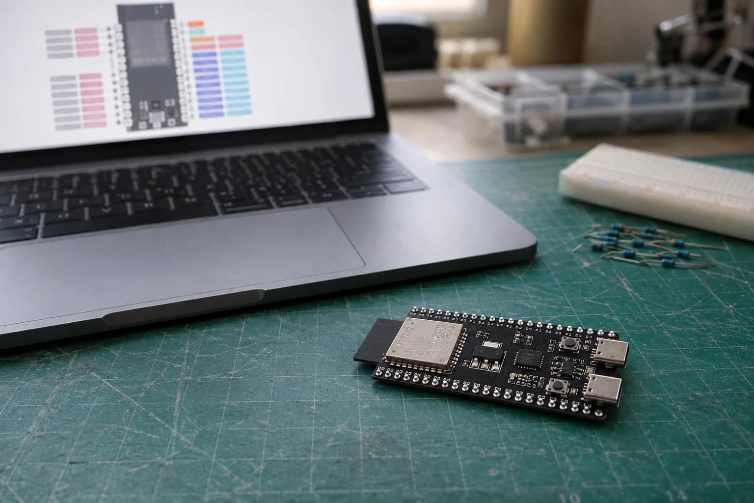
After installing Arduino IDE and completing the first upload in P2, the natural next step is connecting an LED, button, or sensor. It is also where boards stop booting, LEDs stay dark, and GPIO gets damaged because the wrong pinout was used.
P3 is not about memorizing dozens of PINs. I want you to know how to read a pin diagram, choose a low-risk GPIO, and understand why the same sketch cannot use identical pins on every ESP32 board.
The board pinout matters more than the chip pinout
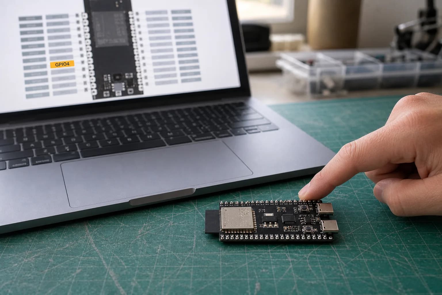
Start with the pinout and schematic for the exact board, module, and revision—not a generic ESP32 image.
A useful pinout must match three things: the board, module, and revision. ESP32-S3 is a chip family, ESP32-S3-WROOM-1-N8R8 is a module, and ESP32-S3-DevKitC-1 v1.1 is the board whose two headers are in your hand.
Do not confuse these labels:
| Label | What it means |
|---|---|
GPIO4, IO4, or 4 | The GPIO number used in pinMode(4, ...) |
3V3, 5V, VBUS | Power rails, not GPIO |
GND | The circuit's common reference |
EN, RST | Chip enable/reset, not a normal GPIO |
TX, RX, SDA, SCL, MOSI... | Default or suggested peripheral functions; find the underlying GPIO number |
Header position J1-4 | A connector position, not GPIO4 |
The ESP32 GPIO Matrix can route many digital peripheral signals to different pins. “Routable” does not mean every pin is equivalent: analog, USB, high-speed flash, and some special functions still have hardware restrictions.
Open the ESP32 Pinout Diagram & Comparison Guide, choose the exact development kit, and click a pin to see its functions and warnings. If a marketplace image disagrees with the manufacturer's schematic, I trust the schematic.
Five pin groups to recognize first
1. Power pins
ESP32 GPIO uses 3.3 V logic. HIGH is normally near 3.3 V and LOW near 0 V. A board may expose 5V or VBUS as a power rail, but that does not make its GPIO 5 V tolerant.
Espressif specifies 3.6 V as the GPIO voltage tolerance. If a 5 V module sends a signal back to the ESP32, use a suitable voltage divider or level shifter. Do not connect it directly just because it survived one test.
2. General-purpose GPIO
These are the best candidates for a first LED, button, or simple peripheral. The common Arduino operations are:
pinMode(pin, OUTPUT);
digitalWrite(pin, HIGH);

pinMode(pin, INPUT_PULLUP);
int level = digitalRead(pin);
An output GPIO is a control signal, not a power source for a motor, relay, servo, or LED strip. Larger or inductive loads need a transistor/MOSFET, protection diode, and an appropriate power supply.
3. Strapping pins
The chip samples strapping pins during reset to choose its boot mode or hardware configuration. Many can act as GPIO after boot, but an external circuit must not force the wrong level while the chip starts.
For example, ESP32-C3 uses GPIO2, GPIO8, and GPIO9 as strapping pins; GPIO8 also drives the RGB LED on C3-DevKitM-1. ESP32-S3 and classic ESP32 have different lists, so never copy a “safe pins” table from another chip family.
4. Pins already used by board hardware
Flash, PSRAM, USB, USB-to-UART, RGB LEDs, cameras, and onboard displays can consume GPIO. On classic ESP32-DevKitC, D0, D1, D2, D3, CMD, and CLK connect to flash and should be avoided. On some ESP32-S3 modules with Octal flash/PSRAM, GPIO35–37 are not available for external use.
5. Pins with special limitations
Classic ESP32 GPIO34–39 are input-only and do not support software-enabled pull-up or pull-down. That is a limitation of the original ESP32, not a universal C3 or S3 rule. ADC, touch, RTC, and USB capabilities also change between chip families.
Pick two pins for the exercise
This exercise uses one loose red LED, a 330 Ω resistor, and a push button. Set the constants for your board:
| Board | LED_PIN | BUTTON_PIN | Note |
|---|---|---|---|
| ESP32-C3-DevKitM-1 | GPIO4 | GPIO5 | Avoid RGB GPIO8 and strapping GPIO2/8/9 |
| ESP32-S3-DevKitC-1 | GPIO4 | GPIO5 | Check the module variant before later using GPIO35–37 |
| Classic ESP32-DevKitC WROOM | GPIO23 | GPIO22 | Avoid flash, UART0, and strapping pins for this first test |
These are convenient choices for the specific DevKits in the table, not a promise that they are free on every commercial board. Check the schematic first when your board includes a display, camera, or sensor.
GPIO output: wire an LED correctly
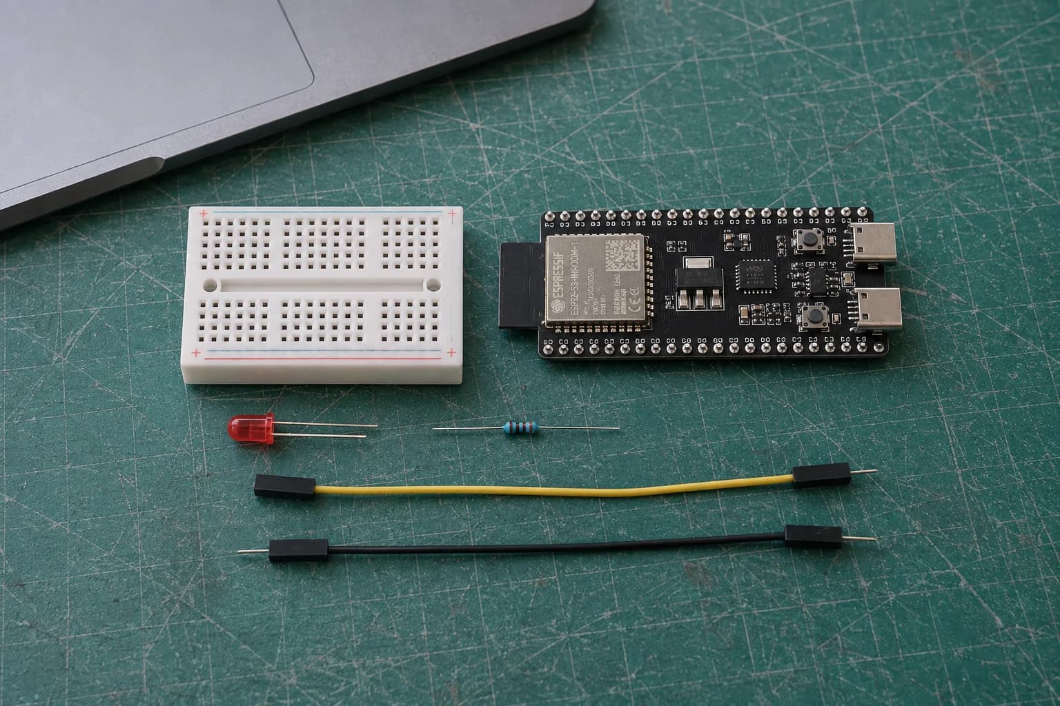
Remove power before wiring; an LED needs a current-limiting resistor, and larger loads need a driver.
Disconnect USB before changing the wiring:
- Connect the selected GPIO to one end of a 330 Ω resistor.
- Connect the resistor's other end to the LED's long anode lead.
- Connect the short cathode lead—the side with the flat LED edge—to GND.
The resistor can sit before or after the LED as long as both components are in series. Do not place the LED directly between GPIO and GND without current limiting.
A minimal Blink sketch is:
constexpr uint8_t LED_PIN = 4; // C3/S3; use 23 for classic ESP32 in the table

void setup() {
  pinMode(LED_PIN, OUTPUT);
  digitalWrite(LED_PIN, LOW);
}

void loop() {
  digitalWrite(LED_PIN, HIGH);
  delay(500);
  digitalWrite(LED_PIN, LOW);
  delay(500);
}
If the LED stays dark, check polarity, breadboard rows, common GND, and the GPIO number before increasing voltage or removing the resistor.
GPIO input: stop floating with a pull-up
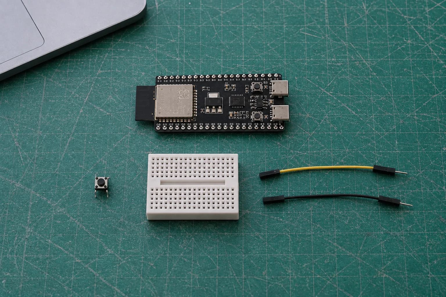
Once wired between GPIO and GND, INPUT_PULLUP reads HIGH when released and LOW when pressed.
An unconnected input is high-impedance and can randomly move between HIGH and LOW as your hand or a wire approaches it. INPUT_PULLUP enables an internal resistor to give the pin a stable default state.
The button wiring is simple:
- Connect one side of the button to
BUTTON_PIN. - Connect the opposite side to GND.
- This test needs no external resistor because it uses
INPUT_PULLUP.
The logic is inverted from what many beginners expect: released = HIGH, pressed = LOW. This sketch lights the LED while the button is held:
constexpr uint8_t LED_PIN = 4;    // C3/S3
constexpr uint8_t BUTTON_PIN = 5; // C3/S3

bool lastPressed = false;

void setup() {
  Serial.begin(115200);
  pinMode(LED_PIN, OUTPUT);
  pinMode(BUTTON_PIN, INPUT_PULLUP);
}

void loop() {
  const bool pressed = digitalRead(BUTTON_PIN) == LOW;
  digitalWrite(LED_PIN, pressed ? HIGH : LOW);

  if (pressed != lastPressed) {
    Serial.println(pressed ? "Pressed" : "Released");
    lastPressed = pressed;
  }

  delay(20); // simple debounce for this exercise
}
For the classic ESP32 board in the table, change the constants to 23 and 22. When a project must capture fast edges without polling, ESP32 supports attachInterrupt(), but an ISR must remain short and does not fix mechanical button bounce.
Measure instead of trusting wire colors
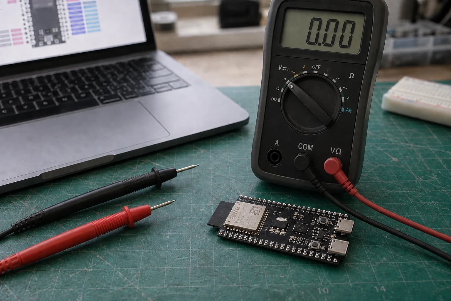
Select the correct sockets and DC range first; signals above 3.6 V need a divider or level shifter.
Dupont wire colors do not guarantee their purpose. Before connecting an unfamiliar module, I usually:
- Measure the voltage between its VCC and GND.
- Check whether the module's output signal rises to 5 V.
- Confirm that the ESP32 and module share GND.
- Turn power off before moving a wire to another pin.
Never measure resistance or continuity on a powered circuit. For voltage, put the black lead in COM, the red lead in the voltage socket, and select the correct DC range. These small checks are more reliable than guessing from wire colors or a product photo.
My GPIO selection workflow
- Record the exact chip, module, board, and revision.
- Open the matching pinout and schematic.
- Eliminate power, reset, flash/PSRAM, and pins not exposed on headers.
- Mark strapping pins, USB, debug UART, and onboard hardware.
- Choose an unused general-purpose GPIO and store it in a named constant.
- Wire with power removed, check continuity when needed, and restore power.
- Test each input or output alone before running the full sensor or motor circuit.
This takes a few extra minutes up front and saves hours of debugging later. It also makes the code intentional: STATUS_LED_PIN explains far more than a bare 4 repeated throughout a sketch.
Checklist before P4
- You can distinguish a GPIO number from a physical header position.
- You never feed a 5 V signal directly into a 3.3 V GPIO.
- LEDs have current-limiting resistors; motors and relays have separate drivers.
- Inputs cannot float because they use an appropriate pull-up, pull-down, or external resistor.
- You checked strapping pins, flash/PSRAM, USB, and onboard hardware.
- GPIO assignments use named constants and match the board schematic.
In P4: Connecting Sensors, we will apply this foundation to digital, analog, and I2C sensors, then build a practical BME280 example.
References
Share
Keep exploring
Read next
Related articles
ESP32 Beginner Guide – P5: Wi-Fi and Web Server
Connect ESP32 to Wi-Fi, find its IP address, and build a local web server that displays BME280 temperature, humidity, and pressure in a browser.
ESP32 Beginner Guide – P6: Bluetooth Low Energy
Learn ESP32 BLE, GATT services, and characteristics by sending BME280 readings to a phone with Read and Notify.
ESP32 Beginner Guide – P7: Build a Complete ESP32 Project
Finish the series with a Room Comfort Monitor: ESP32 reads a BME280, controls a warning LED and serves a local Wi-Fi dashboard.